Preparation method and application of multi-stage structure TiO2/C@MOF nanofiber membrane photo-catalytic material

A technology of photocatalytic materials and nanofiber membranes, applied in the field of preparation and application of composite photocatalytic materials, to achieve the effects of improved utilization, excellent photocatalytic activity, and high yield

Pending Publication Date: 2020-02-07
BEIJING UNIV OF TECH
View PDF5 Cites 2 Cited by
  • Summary
  • Abstract
  • Description
  • Claims
  • Application Information

AI Technical Summary

Problems solved by technology

However, how to obtain MOFs-based composite photocatalytic materials with strong electron-hole separation abili

Method used


Image

  • Preparation method and application of multi-stage structure TiO2/C@MOF nanofiber membrane photo-catalytic material
  • Preparation method and application of multi-stage structure TiO2/C@MOF nanofiber membrane photo-catalytic material
  • Preparation method and application of multi-stage structure TiO2/C@MOF nanofiber membrane photo-catalytic material

Examples


Embodiment 1

[0022] Step 1: Dissolve 3 mL of tetrabutyl titanate and 2 g of PAN in 20 mL of N,N-dimethylformamide, transfer to a syringe with a stainless steel needle, and spin in an electrospinning device with tin foil as a collector Electrospinning was carried out at a solution flow rate of 0.5 mL / h. The resulting film was removed from tinfoil on glass and dried under vacuum at room temperature

[0023] The second step: at 5°C min -1 The heating rate is raised to 380 ° C for 1 hour to obtain TiO 2 / C fiber membrane.

[0024] Step 3: Weigh 4mL (0.02mol / L) of zinc nitrate and 4ml (0.16mol / L) of 2-methylimidazole solution and dissolve them in water. After sonicating and obtaining a homogeneous solution, 0.02 g of TiO 2 / C fiber membrane, keep the temperature at 40°C for 5 hours. Remove, wash, dry.

[0025] Step 4: Weigh 20 mg of the catalyst and a small amount of water, use a 300W xenon lamp as the light source for the photocatalysis experiment, and use carbon dioxide as the reaction ...

Embodiment 2

[0027] Step 1: Dissolve 2 mL of tetrabutyl titanate and 1 g of PAN in 20 mL of N,N-dimethylformamide, transfer to a syringe with a stainless steel needle, and spin in an electrospinning device with tin foil as a collector Electrospinning was carried out at a solution flow rate of 0.7 mL / h. The resulting film was removed from tinfoil on glass and dried under vacuum at room temperature

[0028] The second step: at 10°C min -1 The heating rate is raised to 800 ° C for 2 hours to obtain TiO 2 / C fiber membrane.

[0029] Step 3: Weigh 3mL (0.05mmol / L) zinc nitrate and 3ml (0.3mmol / L) 2-methylimidazole solution and dissolve in water. After sonicating and obtaining a homogeneous solution, 0.03 g of TiO 2 / C fiber membrane, kept at 25°C for 6 hours. Remove, wash, dry.

[0030] Step 4: Weigh 10 mg of the catalyst and a small amount of water, use a 150W xenon lamp as the light source for the photocatalysis experiment, and use carbon dioxide as the reaction atmosphere. First, equil...


PUM


Abstract

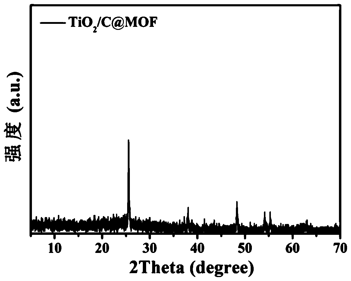
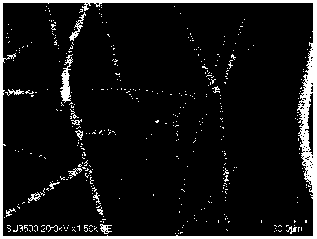
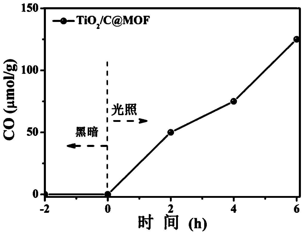
The invention discloses a preparation method and application of a multi-stage structure TiO2/C@MOF nanofiber membrane photo-catalytic material, and belongs to the field of preparation and applicationof composite photo-catalytic materials. In the preparation method, TiO2/PAN is used as a precursor to obtain a carbon-coated titanium dioxide nanofiber membrane TiO2/C through carbonization, then a MOF is grown in situ, and the multi-stage structure TiO2/C@MOF fiber membrane with excellent performance of photo-catalytic reduction of carbon dioxide is constructed. The prepared fiber membrane photo-catalyst not only maintains the advantages of the precursor TiO2/PAN self-supporting fiber membrane, but also maintains the original skeletal structure characteristics of MOFs, and has a relatively large specific surface area which is conducive to capture of a reaction substrate and diffusion of a product. Moreover, a utilization rate of sunlight is increased (MOF can capture visible light) due tothe synergistic effect of TiO2 and MOF, and the formed heterojunction with fully exposed active sites, and thereby the photo-catalyst is used to catalyze reduction of carbon dioxide to generate carbon monoxide.

Description

technical field [0001] The invention belongs to the field of preparation and application of composite photocatalytic materials, in particular to a TiO 2 / C@Metal organic framework fiber membrane photocatalytic material preparation method and application. Background technique [0002] With the global energy crisis and environmental pollution becoming more and more serious, it is imperative to develop and utilize green and environmentally friendly renewable energy. Solar energy is currently one of the cleanest, most durable and most promising renewable energy sources in the world. Among the various strategies for solar energy utilization, photocatalysis is one of the very important research fields to realize the conversion of solar energy into chemical energy. Photocatalytic material semiconductors have broad application prospects in the fields of environmental protection and clean energy due to their chemical stability, low cost and high efficiency. However, most semicondu...

Claims


Application Information

Patent Timeline
IPC IPC(8): B01J31/38B01J31/22B01J35/06C01B32/40
CPCB01J31/38B01J31/1691B01J35/004B01J35/065C01B32/40B01J2531/26B01J2531/0216B01J2231/62
Inventor 李建荣周阿武赵琛周健谢亚勃
Owner BEIJING UNIV OF TECH
Why Eureka
Try Eureka