A method for post-treatment of working fluid for producing hydrogen peroxide by anthraquinone method

A hydrogen peroxide, working fluid technology, applied in chemical instruments and methods, peroxide/peroxyhydrate/peroxyacid/superoxide/ozone, inorganic chemistry, etc., can solve the phosphorus index of acidic wastewater It can reduce the influence of phosphorus-containing indicators, ensure intrinsic safety, and strengthen the ability to resist risks.

Active Publication Date: 2022-05-06
CHINA PETROLEUM & CHEM CORP +1
View PDF5 Cites 0 Cited by
  • Summary
  • Abstract
  • Description
  • Claims
  • Application Information

AI Technical Summary

Problems solved by technology

[0007] Problem: Hydrogen peroxide decomposes violently when encountering alkali, and the high acid-base conversion frequency of the circulating working fluid leads to intrinsic safety hazards of the device; the extensive use of phosphoric acid leads to high phosphorus content in acidic wastewater, resulting in a large amount of phosphorus entering the sewage, forming environmental protection pressure
[0010] Problem: The regeneration of the working fluid used to produce hydrogen peroxide and the treatment of the raffinate must be in an alkaline environment to function. When the device is running unstable and produces more degradation products, this method cannot regenerate the working fluid, resulting in The operating condition of the device continues to deteriorate; when the extraction conditions are poor and the hydrogen peroxide content in the raffinate is high, the vacuum dehydration method cannot meet the post-processing requirements
Therefore, in the industrial application of the regeneration process, the regeneration agent alumina is replaced very frequently and the cost is extremely high

Method used


Image

  • A method for post-treatment of working fluid for producing hydrogen peroxide by anthraquinone method
  • A method for post-treatment of working fluid for producing hydrogen peroxide by anthraquinone method
  • A method for post-treatment of working fluid for producing hydrogen peroxide by anthraquinone method

Examples


Embodiment 1

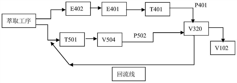
[0061] The raffinate in system A is preheated to 55°C through the heat exchanger (E402), then heated to 85°C through the vacuum feed heater (E401), and then dehydrated and dried in the vacuum drying tower (T401) , the pressure of the vacuum drying tower is 10.5KPa.

[0062] The flow distribution is shown in Table 1:

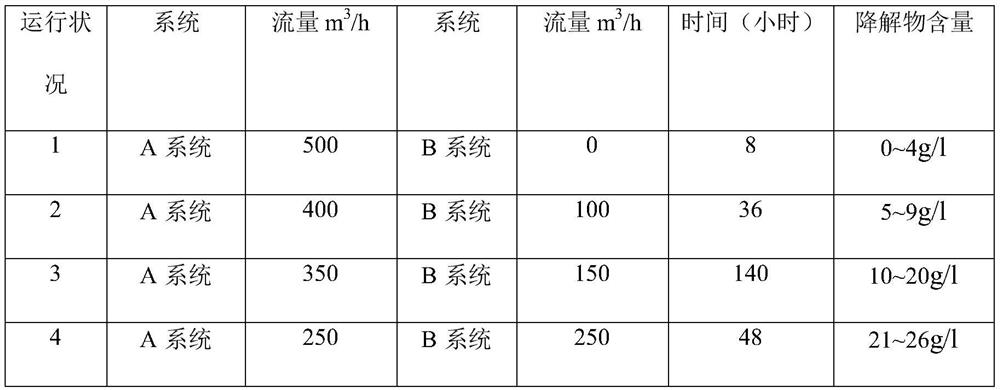
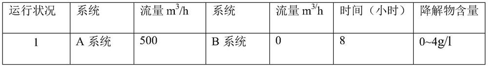
[0063] Table 1 Example 1 flow distribution table

[0064]

[0065] During the 232 hours of operation, the hydrogen efficiency is 7.0-7.5g / l, and the content of degradation products in the working fluid system is gradually and stably controlled between 11-18g / l. The flow rate of system A is 350m for three consecutive months. 3 / h, the flow rate of system B is 150m 3 Under the operation mode of / h, the content of degradation products in the working fluid system is still stably controlled between 11-18g / l, the raffinate index is controlled below 0.15g / l, and the total anthraquinone in the working fluid system is kept between 125-135g / l During the period, the p...

Embodiment 2

[0067] The raffinate in system A is preheated to 55°C through the heat exchanger (E402), then heated to 85°C through the vacuum feed heater (E401), and then dehydrated and dried in the vacuum drying tower (T401) , the pressure of the vacuum drying tower is 11KPa.

[0068] The flow distribution is shown in Table 2:

[0069] Table 2 Example 2 flow distribution table

[0070] operating status system Flow m 3 / h

[0071] During the 232 hours of operation, the hydrogen efficiency is 7.0-7.5g / l, and the content of degradation products in the working fluid system is gradually controlled between 10-15g / l, and the flow rate of system A is 322m for three consecutive months. 3 / h, the flow rate of system B is 72m 3 Under the operation mode of / h, the content of degradation products in the working fluid system is still stably controlled between 10-15g / l, the raffinate index is controlled below 0.15g / l, and the total anthraquinone in the working fluid system is kept betwe...

Embodiment 3

[0073] The raffinate in system A is preheated to 55°C through the heat exchanger (E402), then heated to 85°C through the vacuum feed heater (E401), and then dehydrated and dried in the vacuum drying tower (T401) , the pressure of the vacuum drying tower is 11.5KPa.

[0074] The flow distribution is shown in Table 3:

[0075] Table 3 Example 3 traffic distribution table

[0076] operating status system Flow m 3 / h

[0077] During the 232 hours of operation, the hydrogen efficiency is 7.0-7.3g / l, and the content of degradation products in the working fluid system is gradually controlled between 10-16g / l, and the flow rate of system A is 348m for three consecutive months. 3 / h, the flow rate of system B is 150m 3 Under the operation mode of / h, the content of degradation products in the working fluid system is still stably controlled between 10-16g / l, the raffinate index is controlled below 0.15g / l, and the total anthraquinone in the working fluid system is kept...


PUM


Abstract

The invention discloses a method for post-processing the working liquid of the hydrogen peroxide produced by the anthraquinone method. The raffinate working liquid obtained from the extraction process of the hydrogen peroxide produced by the anthraquinone method can enter the A system and the B system respectively through two pipelines for drying. treatment, and then enter the clay bed (V102) after mixing in the head tank (V320) to obtain the regenerated working fluid; the A system includes a heat exchanger (E402), a vacuum feed heater (E401), a vacuum drying tower (T401 ); the B system includes an alkali tower (T501), a separator (V504); the flow of the raffinate working fluid into the A system and the B system is distributed according to the content of the degradation product in the working fluid; through the present invention, according to the degradation Under the process control of the content of degraded substances, after a period of operation, the system will reach an equilibrium state, and the content of degraded products will be controlled within the range of 10-20g / l. The operation is safe and stable. At the same time, the phosphorus content of wastewater is controlled below 150mg / l. Meet industrial environmental protection emission standards.

Description

technical field [0001] The invention belongs to the technical field of hydrogen peroxide production, and in particular relates to a working fluid post-treatment process system and method for producing hydrogen peroxide by an anthraquinone method. Background technique [0002] Hydrogen peroxide (its aqueous solution is called hydrogen peroxide), the molecular formula is H 2 o 2 , is a strong oxidant that can be mixed with water in any ratio. h 2 o 2 In addition to being widely used in the three major fields of bleaching, chemical synthesis and environmental protection, there are also more and more applications in the fields of food, medicine and hygiene, and the electronics industry. Especially with the development of titanium-silicon molecular sieve catalysts, H 2 o 2 As a green oxidant, it has been widely used in the synthesis of many petrochemical products, such as propylene oxide, epichlorohydrin, quinone, caprolactam, benzaldehyde and phenylacetaldehyde. [0003] ...

Claims


Application Information

Patent Timeline
Patent Type & Authority Patents(China)
IPC IPC(8): C01B15/023
CPCC01B15/023
Inventor 胡元旭苏成芝雷曼胡勤学
Owner CHINA PETROLEUM & CHEM CORP
Why Eureka
Try Eureka