Incineration device and method for treating sulfur recovery tail gas

A technology of sulfur recovery tail gas and incineration device, applied in the chemical industry, can solve the problems of mixing, no recovery of flue gas waste heat, high cost, and achieve the effects of increasing operating pressure, preventing leakage and preventing acid corrosion

Inactive Publication Date: 2020-02-14
BEIJING HANGHUA ENERGY SAVING ENVIRONMENTAL PROTECTION TECH CO LTD
View PDF6 Cites 2 Cited by
  • Summary
  • Abstract
  • Description
  • Claims
  • Application Information

AI Technical Summary

Problems solved by technology

[0009] The problems of this process are: ① due to the limitation of catalyst performance, there is still a part of SO after passing through the hydrogenation reactor 2 The hydrogenation reaction with organic sulfur has not been completed, so it is mixed into the tail gas incinerator; ② Due to the influence of the reaction balance, there is still some H in the tail gas 2 S is not absorbed, and this part of hydrogen sulfide is also mixed into the incinerator
[0012] The problem of this process is: due to the limitation of the performance of the selective oxidation catalyst, the degree of improvement of the conversion rate is limited, and about 1% of sulfides still enter the tail gas incineration device, resulting in SO in the exhaust flue gas. 2 Unable to meet emission standards
[0015] However, there are still obvious problems in this process: ① Due to the low calorific value of the sulfur recovery tail gas, a large amount of gas is required for supplementary combustion during incineration, which is costly; ② Due to the unreasonable design of the burner, NOx emissions often fail to meet the standard; ③ Flue gas Waste heat is not recovered, resulting in energy waste
④The system operates under positive pressure, which may easily cause harmful gas leakage and does not meet the relevant requirements of GB18484

Method used


Image

  • Incineration device and method for treating sulfur recovery tail gas

Examples


Embodiment Construction

[0053] The present invention will be further explained and described below in conjunction with preferred embodiments of the present invention and accompanying drawings.

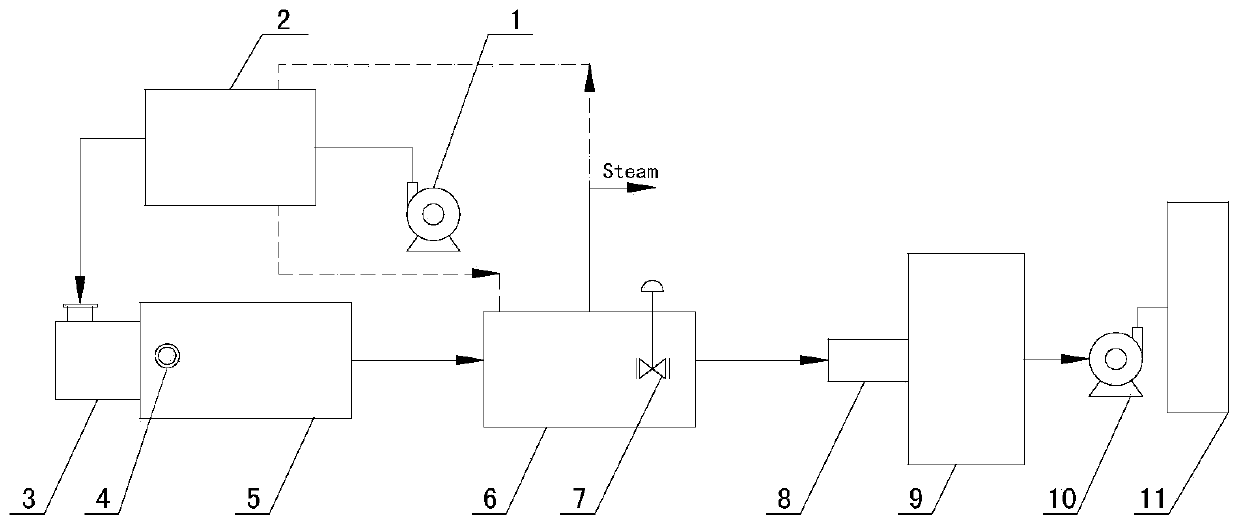
[0054] Such as figure 1 As shown, an incineration device for treating sulfur recovery tail gas includes a blower 1, an air preheater 2, a burner 3, an incinerator 5, a waste heat boiler 6, a quencher 8, an alkali washing tower 9, and an induced draft fan 10 connected in sequence. and the chimney 11, and the mixing inlet 4 located at the front end of the incinerator 5 furnace, the inlet end of the mixing inlet 4 includes a first inlet and a second inlet, and the first inlet is used to transport tail gas to be treated, and the second inlet and The outlet end of the air preheater 2 is connected.

[0055] 1. Blower 1 is used to inhale air and generate combustion-supporting air to enter air preheater 2;

[0056] 2. The air preheater 2 is used to heat the combustion-supporting air to generate heated combustion-supp...


PUM


Abstract

The invention discloses an incineration device and method for treating sulfur recovery tail gas, and belongs to the technical field of chemical engineering. The device adopts a low-NOx burner, and theNOx content can be controlled to be smaller than 100mg/m <3> by controlling oxygen deficiency. According to the device and method, an air preheater is adopted to heat combustion-supporting air, and 20%-30% of fuel can be saved; a waste heat boiler is further adopted to recover waste heat in flue gas, and the energy-saving purpose is achieved through the arrangement of the air preheater and the waste heat boiler; a waste heat boiler center pipe adjusting valve is adopted to adjust the heat exchange flue gas amount, meanwhile, the operation pressure of steam is improved, so that the flue gas temperature is larger than the acid dew point temperature, and acid corrosion of equipment can be effectively prevented; and an induced draft fan is adopted to guarantee the negative pressure of the whole system, leakage of harmful gas is prevented, and the device and method are safer.

Description

technical field [0001] The invention relates to an incineration device and method for treating sulfur recovery tail gas, belonging to the technical field of chemical industry. Background technique [0002] With the rapid development of my country's petrochemical, coal chemical, natural gas purification and other industries, a large amount of tail gas generated by its supporting sulfur recovery device is discharged into the atmosphere, and the tail gas contains H 2 S, SO 2 , S element and CS 2 and other harmful substances, causing serious environmental pollution. [0003] At the same time, due to the rapid development of society, people in contemporary society pay more attention to environmental protection, and many laws and regulations related to environmental protection have also been proposed around the world. [0004] On May 16, 2015, the Ministry of Environmental Protection of my country issued the "Petroleum Refining Industry Pollutant Discharge Standard" (GB31570) a...

Claims


Application Information

Patent Timeline
Patent Type & Authority Applications(China)
IPC IPC(8): F23G7/06F23G5/46F23G5/44F23L15/04F23J15/02B01D53/18B01D53/14
CPCB01D53/1481B01D53/18F23G5/44F23G5/46F23G7/06F23G2206/201F23G2209/14F23J15/02F23L15/04Y02E20/34Y02P20/10
Inventor 张武龙王亚飞时明伟骆骞尚玉光蒋海亮杜方涛王星凯贺思鞠
Owner BEIJING HANGHUA ENERGY SAVING ENVIRONMENTAL PROTECTION TECH CO LTD
Why Eureka
Try Eureka