
Post-welding shaping method and welding method for metal target material

A metal target and post-welding technology, which is applied in the post-welding shaping method and welding field of metal targets, can solve problems such as target deformation, unusable metal targets, and complicated processing methods, and achieve improved yield and high industrial application value, the effect of solving the problem of cracking

Active Publication Date: 2020-02-21
KONFOONG MATERIALS INTERNATIONAL CO LTD
View PDF9 Cites 11 Cited by
  • Summary
  • Abstract
  • Description
  • Claims
  • Application Information

AI Technical Summary

Problems solved by technology

[0006] CN106702333A discloses a manufacturing method of a target assembly, which uses diffusion welding to add a buffer layer with a thermal expansion system between the target and the back plate to play a role in stress buffering, so that the target assembly When cooling from high temperature to room temperature, the diffusion interface stress between the target and the buffer layer is small, which avoids the fracture of the target to a certain extent, but this method needs to find different buffer layer materials for different target materials and backplane materials. not universal
[0007] CN108468025A discloses a hot isostatic pressing treatment method for a chromium plane target, which minimizes the deformation of the target workpiece by using ceramic beads with small thermal deformation and fluidity, and reduces side bending and deformation, but the method The processing method is more complicated, and the target will still be deformed to a certain extent, and the improvement of the post-shaping method is not considered
[0008] CN204342868U discloses a powder metallurgy diffusion welding target, by adding a transition layer between the target and the back plate, the overall deformation of the welded target is small and does not crack, but the target still deforms after welding , cannot be used directly as a sputtering target
[0009] To sum up, the target assembly will have a certain deformation after welding, but the existing improved process is still difficult to guarantee the flatness and yield of the target, and the deformation of the target is less improved. Therefore, it is necessary to reshape the deformed target to ensure Ensure target flatness and thickness uniformity
[0010] However, metal targets are made of powder metallurgy or made of brittle metal materials, such as W, WSi, TiAl, TaSi, CrSi and other targets. After welding, there is a large gap with the back plate material such as aluminum alloy or copper alloy. Due to the difference in thermal expansion coefficient, if a large deformation occurs, if it is directly leveled with a press, cracks or micro-cracks are prone to occur due to the brittleness of the metal target, making the metal target unusable

Method used


Image

  • Post-welding shaping method and welding method for metal target material
  • Post-welding shaping method and welding method for metal target material
  • Post-welding shaping method and welding method for metal target material

Examples


Embodiment 1

[0088] This embodiment provides a method for shaping a metal target after welding. The method includes the following steps:

[0089] (1) Put the target component A in a heating furnace and keep it at 350℃ for 1h;

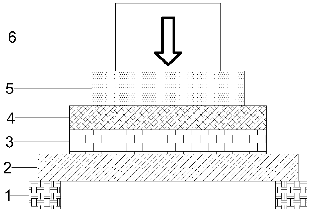
[0090] (2) such as figure 1 As shown, above the target 3 of the target assembly A after heating, a silicone pad 4 with a thickness of 11 mm and a pad 5 with a thickness of 30 mm are arranged in the center on the basis of the target assembly A. A gasket 1 with a thickness of 20mm is centrally arranged under the back plate 2 based on the target assembly A;

[0091] Wherein, the silica gel pad 4 has a hardness of 45HA and a tensile strength of 75kg / cm 2 The diameter of the silicone pad 4 is 410mm, the diameter of the pad 5 is 200mm, and the material is pure aluminum 1060, the inner diameter of the gasket 1 is 430mm, the outer diameter is 470mm, and the material is stainless steel 361;

[0092] (3) The target assembly A is pressurized and shaped by a hydraulic press 6 at a pre...

Embodiment 2

[0094] This embodiment provides a method for shaping a metal target after welding. The method is the same as the embodiment 1 except that the heating operation of step (1) is not performed.

Embodiment 3

[0096] This embodiment provides a method for shaping a metal target after welding. The method except step (2) does not place a gasket with a thickness of 20 mm under the back plate of the target assembly A based on the target assembly A. Same as Example 1, its step (2) is specifically:

[0097] (2) A silicone pad with a thickness of 11 mm and a spacer block with a thickness of 30 mm are arranged in the center above the target of the target assembly A after heating, taking the target assembly A as a reference;

[0098] Wherein, the silicone pad has a hardness of 45HA and a tensile strength of 75kg / cm 2 The diameter of the silicone pad is 410mm, the diameter of the pad is 200mm, and the material is pure aluminum 1060.


PUM

PropertyMeasurementUnit
Tensile strengthaaaaaaaaaa
Thicknessaaaaaaaaaa
Tensile strengthaaaaaaaaaa

Abstract

The invention provides a post-welding shaping method for a metal target material. According to the method, a buffer cushion and a cushion block are sequentially arranged above the target material of atarget material assembly, and then pressing shaping is carried out, wherein the hardness of the buffer cushion is 30-60HA, the tensile strength is 50-100kg / cm<2>, the problem that penetrating cracksand a cracking phenomenon easily occur due to a great pressure instantaneously born by the surface of the target material in a shaping process is alleviated well, good protection and buffer effects are acted on the target material, and the yield of the target material is increased; and the target material is heated before shaping and a washer is arranged below a back plate of the target material assembly, so that the shaping efficiency of a shaping machine for the target material is increased and the planeness of the target material after shaping is improved, and a high industrial applicationvalue is achieved.

Description

Technical field [0001] The invention relates to the field of semiconductor technology, and in particular to a method for shaping a metal target after welding and a welding method. Background technique [0002] Sputtering technology is one of the common processes in the field of semiconductor manufacturing. With the increasing development of sputtering technology, sputtering targets play an increasingly important role in sputtering technology. The quality of sputtering targets directly affects the sputtering technology. Film quality after shooting. [0003] There are many manufacturing methods for target components. In the early days, brazing was mainly used. In, Sn and their alloy solders with relatively soft materials were used for welding. The process is simple, but the welding strength is low (within 10MPa) and the melting point of the solder is low. , Unable to meet the needs of high-power sputtering coating. [0004] Therefore, technicians develop diffusion welding methods to ...

Claims


Application Information

Patent Timeline
IPC IPC(8): B21D3/10B21D37/16
CPCB21D3/10B21D37/16
Inventor 姚力军潘杰边逸军王学泽廖培君
Owner KONFOONG MATERIALS INTERNATIONAL CO LTD
Learn More