Current collector electrode structure, secondary battery and preparation method thereof

A technology of electrode structure and secondary battery, which is applied in the direction of secondary battery manufacturing, secondary battery, electrode carrier/collector, etc., can solve problems such as damage, and achieve the effect of ensuring safety performance, integrity, and connection strength

Pending Publication Date: 2020-02-21
JIANGSU ADVANCED MATERIAL TECH CO LTD
View PDF15 Cites 22 Cited by
  • Summary
  • Abstract
  • Description
  • Claims
  • Application Information

AI Technical Summary

Problems solved by technology

[0004] The primary purpose of this application is to provide a current collector electrode structure to solve the problem of tab forming in a new type of current collector in the prior art, avoid damaging the conductive layer during the tab forming process, and improve the safety performance of the battery

Method used


Image

  • Current collector electrode structure, secondary battery and preparation method thereof
  • Current collector electrode structure, secondary battery and preparation method thereof
  • Current collector electrode structure, secondary battery and preparation method thereof

Examples


preparation example Construction

[0096] The present application also provides a method for preparing a secondary battery, comprising the following steps: preparing a current collector electrode, coating the positive or negative active material on the current collector electrode, rolling die-cutting, lamination or winding assembly, liquid injection , into content.

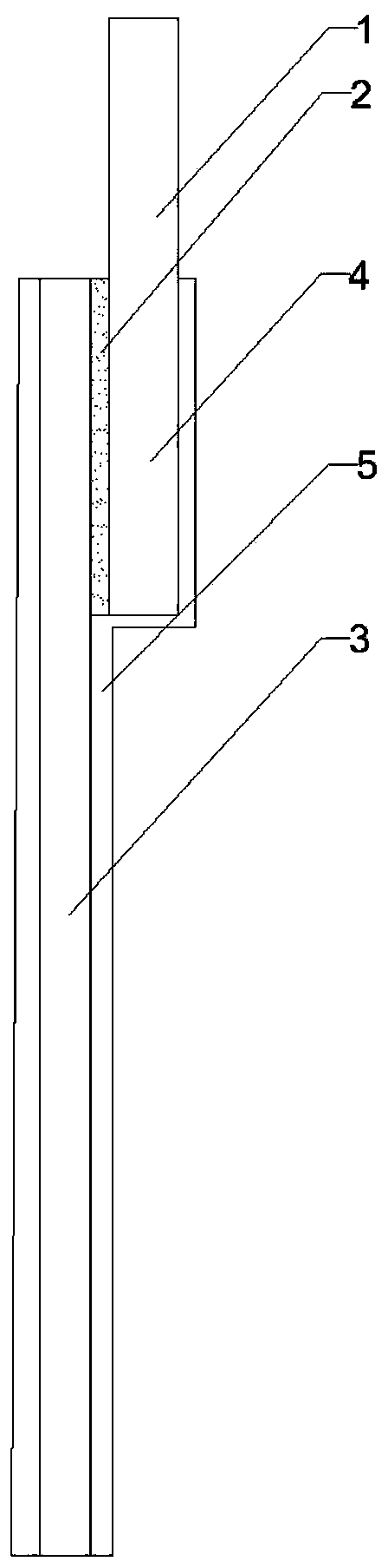
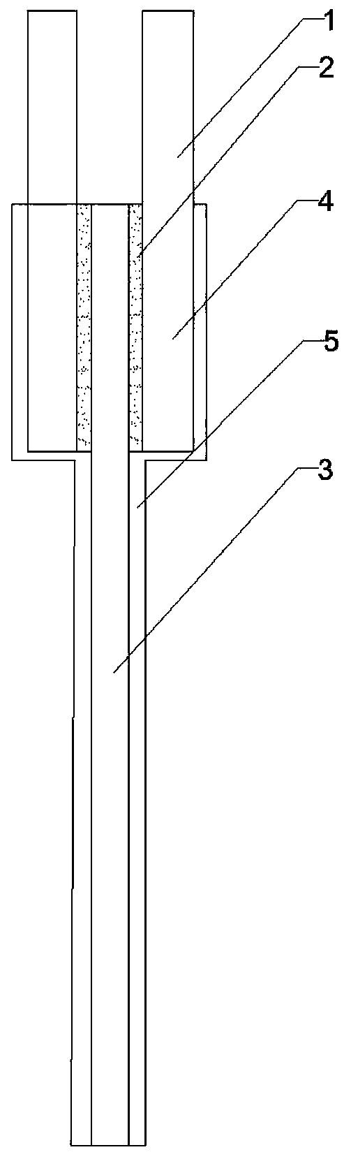
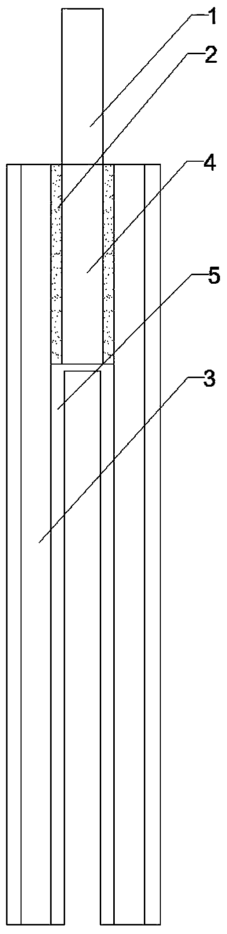
[0097] When preparing the current collector, according to a specific embodiment of the present application, the tabs are first adhered to the insulating layer through an adhesive, and the compounding method can be dry compounding or thermal compounding; A conductive layer forms on the surface of the ear.

[0098] Among them, the formation process of the conductive layer can be selected from physical vapor deposition (PVD), vacuum evaporation, chemical vapor deposition (CVD), atomic layer deposition (ALD), magnetron sputtering, high-power electron beam, molecular beam epitaxy, printing, Coating one or a combination of conductive pastes. In this em...

Embodiment 1

[0103] Take a polypropylene film with a thickness of 10um as the positive electrode insulating layer, take an aluminum foil with a thickness of 10um and a width of 20mm as the positive electrode tab, and adhere the positive electrode tab to the end of the surface of the positive electrode insulating layer. The adhesive is a polymethacrylate adhesive, the bonding strength is 7N / cm, and the width of the composite area of ​​the positive electrode tab and the positive electrode insulating layer is 10mm. Then, a conductive layer is formed on both sides of the adhered positive insulating layer by physical vapor deposition. The material of the conductive layer is aluminum, and the thickness of the conductive layer is 0.5um to form a positive current collector electrode structure.

[0104] Take a polypropylene film with a thickness of 10um as the negative electrode insulation layer, take a copper foil with a thickness of 10um and a width of 20mm as the negative electrode tab, and adher...

Embodiment 2

[0107] A secondary battery was produced by the same method as in Example 1 except that the adhesive used was an epoxy resin adhesive and the adhesive strength was 10 N / cm.


PUM

PropertyMeasurementUnit
widthaaaaaaaaaa
adhesivityaaaaaaaaaa

Abstract

The invention discloses a current collector electrode structure, and relates to the technical field of secondary batteries. The current collector electrode structure in the application comprises a current collector and a tab. The current collector comprises an insulating layer and a conductive layer used for carrying an electrode active material and arranged on at least one surface of the insulating layer. The tab is arranged on the current collector and connected with the current collector through an electrolysis-resistant binder or conductive adhesive, and the bonding strength of the binderor the conductive adhesive is not less than 7N/cm. The tab and the current collector are connected by the binder or the conductive adhesive, so that welding is avoided, and the conductive layer on thesurface of the insulating layer cannot be damaged by the connecting structure of the tab. Besides, the binder or the conductive adhesive used in the application has electrolysis resistance, and the bonding strength of the binder or the conductive adhesive is not less than 7N/cm, so that the connection strength between the tab and the current collector is ensured, and the situation in which the tab is separated from the current collector in the subsequent assembly and use process is avoided.

Description

technical field [0001] The present application relates to the technical field of secondary batteries, in particular to a current collector electrode structure, a secondary battery and a preparation method thereof. Background technique [0002] Secondary batteries, such as lithium-ion batteries, generally consist of a battery cell, an electrolyte, and a battery case. Among them, the batteries mainly include cylindrical batteries, square shell batteries, soft pack batteries, etc. Taking the cylindrical cell as an example, its structure is usually a winding body, which is wound from a positive pole piece, a negative pole piece and a separator. The tab is a component used to lead out electricity in the battery structure, and is usually arranged on the positive pole piece and the negative pole piece respectively, and one end of the tab protrudes from the casing. Specifically, the pole piece is generally composed of a current collector and an active material coated on the surfac...

Claims


Application Information

Patent Timeline
Patent Type & Authority Applications(China)
IPC IPC(8): H01M4/13H01M4/139H01M2/26H01M4/66H01M10/0525H01M10/0585H01M10/0587H01M10/04
CPCH01M4/13H01M4/139H01M4/667H01M10/0525H01M10/0585H01M10/0587H01M10/0431H01M50/538H01M50/531Y02E60/10Y02P70/50
Inventor 王晓明魏凤杰
Owner JIANGSU ADVANCED MATERIAL TECH CO LTD
Why Eureka
Try Eureka