
Preparation method of thin-layer SiO2 passivation film and prepared battery

A passivation film and thin layer technology, applied in the direction of coatings, circuits, electrical components, etc., can solve the problems of easy pollution of the cavity, long process time, high temperature, etc., to achieve highly controllable uniformity, low process temperature, and high speed effect

Active Publication Date: 2020-04-03
江苏杰太光电技术有限公司
View PDF4 Cites 2 Cited by
  • Summary
  • Abstract
  • Description
  • Claims
  • Application Information

AI Technical Summary

Problems solved by technology

[0004] 1) Wet Nitric Acid Oxidation: Oxidize silicon wafers with high-temperature concentrated nitric acid for 4 minutes to form an extremely thin nano-SiO thin layer on the surface with a thickness of about 1.5nm. Environmental friendly;
[0005] 2) Thermal oxidation: Generally, tubular equipment is used, heated to a high temperature of about 570°C, and it takes about 30-60min to grow SiO with a thickness of about 2nm 2 Thin film has the disadvantages of high temperature, high energy consumption, long process time and high cost;
But since SiH 4 met O 2 will burn violently to form SiO 2 Dust particles, so that it is impossible to grow extremely thin SiO on silicon wafers 2 Thin film is also easy to contaminate the cavity, so the tubular equipment can only use N 2 O and SiH 4 As a reactive gas, the result is SiON instead of the desired SiO 2 , due to its grown SiO 2 The film contains higher N elements, and it is a SiON film instead of pure SiO 2 film, so the performance cannot meet the requirements
At the same time, N 2 O cost is also high

Method used


Image

  • Preparation method of thin-layer SiO2 passivation film and prepared battery
  • Preparation method of thin-layer SiO2 passivation film and prepared battery

Examples


Embodiment Construction

[0020] The following will clearly and completely describe the technical solutions in the embodiments of the present invention with reference to the drawings in the embodiments of the present invention.

[0021] The present invention firstly provides a kind of thin-layer SiO2 in batteries such as Topcon, POLO, IBC, PERC etc. 2 The preparation method of passivation film specifically comprises the following steps:

[0022] 1) Firstly, a plasma-excited deposition and coating equipment for chain continuous coating is provided;

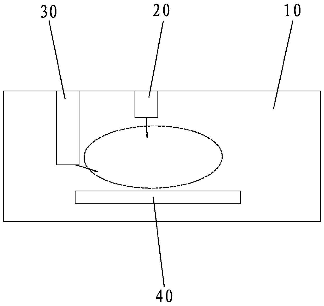
[0023] 2) The carrier plate carrying the silicon wafer 40 is continuously transported to the process chamber 10 of the chain PECVD equipment by a continuous transport mechanism (such as figure 1 Shown) to achieve coating;

[0024] 3) In the process chamber 10, SiH 4 and O 2 The gas is output from different regions respectively, and the gas is output through the gas outlet of the electrode plate of the plasma source 20. 2 , and SiH is released from the ...


PUM


Abstract

The invention discloses a preparation method of a thin-layer SiO2 passivation film. The method specifically comprises the following steps that 1) firstly, a chain type continuous coating PECVD deviceis provided; 2) carrier plates carrying silicon wafers are continuously conveyed into a process cavity of the chain type PECVD device through a continuous conveying mechanism to realize coating; (3) in the process cavity, a gas outlet hole of an electrode plate of a plasma source is used for discharging O2, meanwhile, SiH4 is discharged from a gas distribution block on the side face of the electrode plate of the plasma source, the SiH4 and the O2 enter into different areas of the process cavity through different pipelines and flow out to encounter and mix with each other under vacuum of 1-20 Pa and form SiO2 passivation films on the surfaces of the continuously conveyed silicon wafers. According to the method, only the two specific gases SiH4 and O2 are used as reaction gases, a separatedgas inlet mode is used, so that the method has the advantages of low process temperature, safety, reliability, environmental protection and the like, dynamic chain type continuous coating and growingare achieved, the belt speed is high, the yield is large and uniformity is highly controllable.

Description

technical field [0001] The invention relates to the technical field of high-efficiency solar cell preparation, in particular to SiO2 in batteries such as Topcon, POLO, IBC, and PERC. 2 The preparation method of passivation film and prepared Topcon, POLO, IBC, PERC and other batteries. Background technique [0002] In recent years, with the research and development of crystalline silicon solar cells, both theory and practice have proved that surface passivation is the only way to improve cell efficiency, and aluminum oxide thin layer passivation has been widely promoted on PERC cells. However, the passivation effect of doped polysilicon and silicon oxide stack is better, which is the prospect of the development of next-generation mass production technology. This is due to the chemical passivation effect of silicon oxide on the surface of crystalline silicon, and doped polysilicon has a good field passivation effect. But because silicon oxide is insulating, it prevents inter...

Claims


Application Information

Patent Timeline
IPC IPC(8): C23C16/40C23C16/513C23C16/54H01L31/0216H01L31/18
CPCC23C16/402C23C16/513C23C16/54H01L31/1868H01L31/02167Y02P70/50
Inventor 上官泉元闫路刘宁杰
Owner 江苏杰太光电技术有限公司
Learn More