Efficient rapid dissolving equipment for rare earth production

A high-efficiency, rare-earth technology, applied in the direction of dissolving, dissolving, driving agitator to dissolve, etc., can solve the problems of no layered, framed and chained structures, long time, lack of sulfides and sulfates, etc., to achieve improved stirring Effect, Ease of Dissolution, Effect of Accelerated Dissolution

Inactive Publication Date: 2020-04-07
安徽延创通讯科技有限公司
View PDF0 Cites 4 Cited by
  • Summary
  • Abstract
  • Description
  • Claims
  • Application Information

AI Technical Summary

Problems solved by technology

[0004] One is the lack of sulfides and sulfates (only very few), which shows that rare earth elements are oxophilic;
[0005] Second, the rare earth silicate is mainly island-like, without layered, framed and chained structures;
Due to the large volume of rare earth ore and the long reaction time

Method used


Image

  • Efficient rapid dissolving equipment for rare earth production
  • Efficient rapid dissolving equipment for rare earth production
  • Efficient rapid dissolving equipment for rare earth production

Examples


Embodiment 1

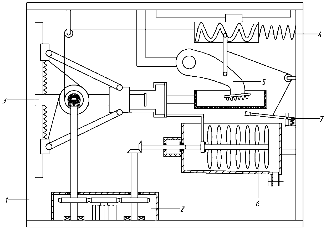
[0061] A high-efficiency rapid dissolution equipment for rare earth production, including a frame 1, a driving assembly 2, a reciprocating assembly 3, a transmission assembly 4, a crushing assembly 5, and a dissolving assembly 6;

[0062] The frame 1 includes a base 101, a left side plate 102, a right side plate 103 and a top plate 104. The left and right sides of the base 101 are fixedly connected with a left side plate 102 and a right side plate 103 respectively, and the top of the left side plate 102 and the right side plate 103 pass through the top plate 104 connection; the left part of the base 101 is provided with a driving assembly 2, and the right side of the left side plate 102 is provided with a reciprocating assembly 3, and the driving assembly 2 cooperates with the reciprocating assembly 3; The feeding hole 106; the pulverization assembly 5 is arranged above the pulverization tank 105, and the pulverization assembly 5 cooperates with the reciprocating assembly 3 thr...

Embodiment 2

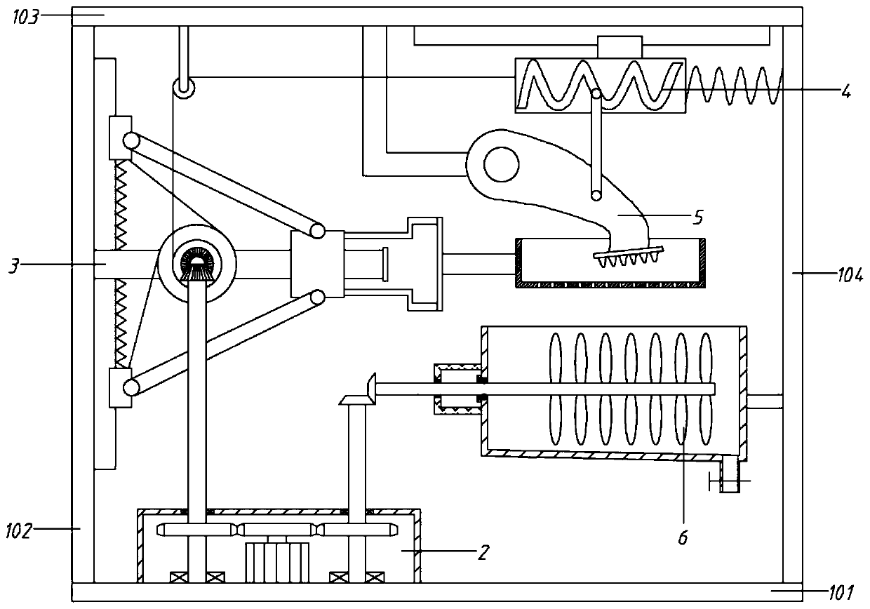
[0064] A high-efficiency rapid dissolution equipment for rare earth production, including a frame 1, a driving assembly 2, a reciprocating assembly 3, a transmission assembly 4, a crushing assembly 5, and a dissolving assembly 6;

[0065] The frame 1 includes a base 101, a left side plate 102, a right side plate 103 and a top plate 104. The left and right sides of the base 101 are fixedly connected with a left side plate 102 and a right side plate 103 respectively, and the top of the left side plate 102 and the right side plate 103 pass through the top plate 104 connection; the left part of the base 101 is provided with a driving assembly 2, and the right side of the left side plate 102 is provided with a reciprocating assembly 3, and the driving assembly 2 cooperates with the reciprocating assembly 3; The feeding hole 106; the pulverization assembly 5 is arranged above the pulverization tank 105, and the pulverization assembly 5 cooperates with the reciprocating assembly 3 thr...

Embodiment 3

[0082] The difference from Example 2 is that

[0083] Among them, the dissolving assembly 6 includes the fourth bevel gear 601, the third rotating shaft 602, the first support plate 604, the third connecting rod 605, the installation plate 606, the outer cylinder 607 and the stirring blade 608;

[0084] The left side of the dissolution box 108 is fixedly connected with a No. 1 support plate 604; the dissolution box 108 is provided with an outer cylinder 607, and the outer cylinder 607 is evenly equipped with stirring blades 608; The No. 4 bevel gear 601 is installed on the left end of the No. 3 rotating shaft 602, and the No. 4 bevel gear 601 and the No. 2 bevel gear 209 are vertically meshed; the No. 3 rotating shaft 602 includes a circular shaft section on the left 6021 and the special-shaped shaft section 6022 on the right. The circular shaft section 6021 passes through the No. 1 support plate 604 and extends into the dissolution tank 108 from the left side.

[0085] Where...


PUM


Abstract

The invention relates to the technical field of dissolving equipment for rare earth production, in particular to efficient rapid dissolving equipment for rare earth production. A servo motor is adopted and controlled to drive a first gear to rotate forwards and backwards, a first bevel gear and a second bevel gear are driven to rotate through transmission, one bevel gear serves as a power source of a reciprocating assembly, and the other bevel gear serves as a power source of a stirring assembly. And when the first bevel gear rotates, the second bevel gear is driven to rotate, and a first take-up wheel rotates to carry out take-up and pay-off. A first-class pull rope is synchronously tightened or loosened under the action of the first take-up wheel, and the first-class pull rope is matchedwith a first-class spring to drive a sliding sleeve to move in the axial direction of a sliding rod through a push-pull rod. The first bevel gear rotates forwards and reversely, namely, the sliding sleeve reciprocates, so that a moving plate moves along with the first bevel gear, a crushing groove moves left and right, and comprehensive crushing is achieved through cooperation with a crushing assembly; and when the second bevel gear rotates, the stirring assembly is driven to work, so that stirring blades generate a stirring and mixing effect to realize rapid dissolution.

Description

technical field [0001] The invention relates to the technical field of dissolution equipment for rare earth production, in particular to a high-efficiency rapid dissolution equipment for rare earth production. Background technique [0002] Rare earth resources are the lanthanide elements in the periodic table of chemical elements—lanthanum (La), cerium (Ce), praseodymium (Pr), neodymium (Nd), promethium (Pm), samarium (Sm), europium (Eu), gadolinium (Gd ), terbium (Tb), dysprosium (Dy), holmium (Ho), erbium (Er), thulium (Tm), ytterbium (Yb), lutetium (Lu), and two closely related to the 15 elements of the lanthanide series Elements - scandium (Sc) and yttrium (Y), a total of 17 elements, called rare earth elements, also called rare earth resources, referred to as rare earth. [0003] The physical and chemical properties of rare earths have the following characteristics: [0004] One is the lack of sulfides and sulfates (only very few), which shows that rare earth elements...

Claims


Application Information

Patent Timeline
IPC IPC(8): B01F13/10B01F15/00B01F1/00B02C1/00B02C23/16B07B1/28
CPCB02C1/00B07B1/28B02C23/16B01F21/10B01F33/831B01F35/322B01F35/3204
Inventor 王雅婷
Owner 安徽延创通讯科技有限公司
Why Eureka
Try Eureka