

Method for electroplating zinc-nickel alloy, magnet, electroplating solution and purpose of potassium chloride
A technology for electroplating zinc-nickel and zinc-nickel alloys, applied in jewelry and other directions, can solve problems such as poor deep plating ability, and achieve the effect of high current efficiency and improved deep plating ability
- Summary
- Abstract
- Description
- Claims
- Application Information
AI Technical Summary
Problems solved by technology
Method used
Image

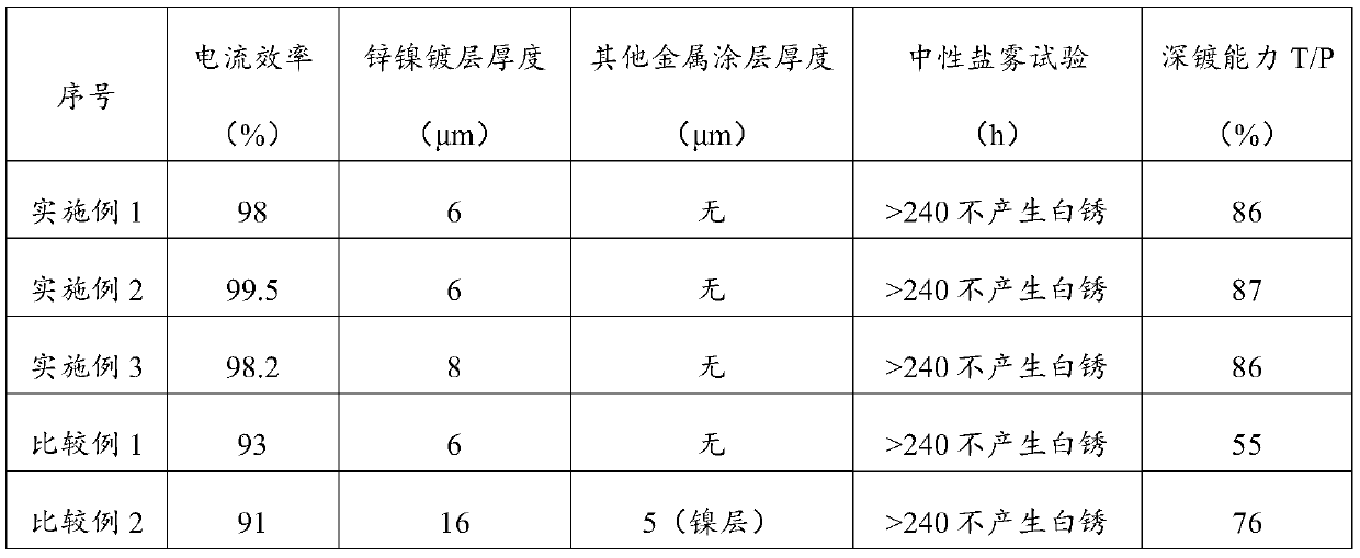
Examples
Embodiment 1
[0098] (1) Manually chamfer the NdFeB magnet, the C angle is 0.3, and then perform vibration chamfering, the R angle is 0.6. Place the chamfered NdFeB magnet in a degreasing agent at 45°C, and perform degreasing treatment under ultrasonic conditions for 45s. The degreasing agent is composed of 13g / L sodium fluoride, 20g / L sodium phosphate, 30g / L cocoate diethanolamine, 20g / L sodium pyrophosphate, 20g / L fatty alcohol polyoxyethylene ether and water. The degreased NdFeB magnet was placed in an aqueous nitric acid solution with a concentration of 10 wt%, and pickled under ultrasonic conditions for 30s. The pickled NdFeB magnet was placed in a citric acid solution with a pH of 3 at 25° C. for 30 seconds for activation treatment to obtain the first magnet.
[0099] (2) The first magnet is placed in an electroplating solution at 35° C. for electroplating to obtain a second magnet. Cathode moving mode is adopted, and the cathode current density is 1.5A / dm -2 . The electroplating ...
Embodiment 2
[0102](1) Manually chamfer the NdFeB magnet, the C angle is 0.5, and then perform vibration chamfering, the R angle is 0.7. Place the chamfered NdFeB magnet in a degreasing agent at 50°C, and perform degreasing treatment under ultrasonic conditions for 30s. The degreasing agent is composed of 15g / L sodium fluoride, 40g / L sodium phosphate, 30g / L cocoate diethanolamine, 25g / L sodium pyrophosphate, 35g / L fatty alcohol polyoxyethylene ether and water. Then, the degreased NdFeB magnet was placed in an aqueous nitric acid solution with a concentration of 10 wt%, and pickled under ultrasonic conditions for 45s. The pickled NdFeB magnet was placed in a citric acid solution with a pH of 3 at 25° C. for 40 seconds for activation treatment to obtain the first magnet.
[0103] (2) The first magnet is placed in an electroplating solution at 35° C. for electroplating to obtain a second magnet. Cathode moving mode is adopted, and the cathode current density is 0.75A / dm -2 . Electroplatin...
Embodiment 3
[0106] (1) Manually chamfer the NdFeB magnet, the C angle is 0.4; then perform vibration chamfering, the R angle is 0.7. Place the chamfered NdFeB magnet in a degreasing agent at 55°C, and perform degreasing treatment under ultrasonic conditions for 30s. The degreasing agent is composed of 10g / L sodium fluoride, 20g / L sodium phosphate, 25g / L cocoate diethanolamine, 20g / L sodium pyrophosphate, 20g / L fatty alcohol polyoxyethylene ether and water. Then, the degreased NdFeB magnet was placed in an aqueous solution of nitric acid with a concentration of 10 wt%, and pickled under ultrasonic conditions for 30 s. The pickled NdFeB magnet was placed in a citric acid solution with a pH value of 2.3 at 25° C. for 40 seconds for activation treatment to obtain the first magnet.
[0107] (2) The first magnet is placed in an electroplating solution at 35° C. for electroplating to obtain a second magnet. Cathode moving mode is adopted, and the cathode current density is 0.75A / dm -2 . The ...
PUM
| Property | Measurement | Unit |
|---|---|---|
| thickness | aaaaa | aaaaa |
Abstract
Description
Claims
Application Information