
Membrane electrode assembly for solid polymer electrolyte electrolytic cell and preparation method

A solid polymer, membrane electrode assembly technology, applied in the direction of electrolysis components, electrodes, electrolysis process, etc., to achieve the effect of reducing ohmic impedance, reducing interface contact impedance, and reducing use cost

Active Publication Date: 2020-05-12
TONGJI UNIV
View PDF7 Cites 5 Cited by
  • Summary
  • Abstract
  • Description
  • Claims
  • Application Information

AI Technical Summary

Problems solved by technology

However, the previous optimization or modification methods rarely achieve high hydrolysis efficiency and long-term operating life while reducing the cost of MEA catalysts, which is not conducive to further improving the scale promotion of solid polymer electrolyzers

Method used


Image

  • Membrane electrode assembly for solid polymer electrolyte electrolytic cell and preparation method
  • Membrane electrode assembly for solid polymer electrolyte electrolytic cell and preparation method
  • Membrane electrode assembly for solid polymer electrolyte electrolytic cell and preparation method

Examples


Embodiment 1

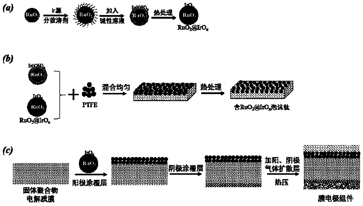
[0029] like figure 2 As shown in (a), 0.075g RuO 2 Added 200ml ethanol solution ultrasonic 30min, 0.025g IrCl 3 Join RuO 2 Continue to sonicate for 30 minutes, then add 0.01M NaOH aqueous solution drop by drop until the pH of the mixed solution is ≥ 10 and keep for two hours. Process 1h to get RuO 2 @IrO x core-shell material.

[0030] like figure 2 (b) shows the resulting RuO 2 @IrO x Mixed with polytetrafluoroethylene (PTFE) according to the mass ratio of 70:30 mechanical ball milling, coated on the surface of foamed titanium, and then treated at 350 ° C for 1 h to obtain the RuO-containing 2 @IrO x Titanium foam, RuO on the surface of titanium foam 2 @IrO x The loading capacity is 0.05mg cm -2 ;

[0031] RuO 2 @IrO x And 5% Nafion solution is dispersed in the mixed solution (isopropanol: water=9:1) of isopropanol water according to mass ratio (80:20) and stirs to obtain slurry, by screen printing method RuO 2 @IrO x Prepared on Nafion 117 as the anode cat...

Embodiment 2

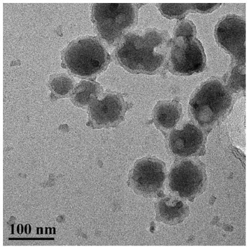
[0033] 0.075g RuO 2 Added 180ml of ethanol and 20ml of water in the mixed solution of ultrasonic 30min, 0.025g H 2 IrCl 6 6H 2 O joined RuO 2 The ethanol-water mixed solution, continue to sonicate for 30min, then add ammonia aqueous solution drop by drop, until the mixed solution is maintained at pH = 12 for two hours, collect the resulting precipitate, place it in a vacuum oven for drying at 80°C, and then dry it in a vacuum oven at 400°C Treat at ℃ for 1h to get RuO 2 @IrO x core-shell material. image 3 For the prepared RuO 2 @IrO x For the core-shell sample, it can be seen that the RuO 2 The size of the core is about 85nm, and the outer shell is IrO x About 8nm.

[0034] The RuO obtained above 2 @IrO x The dried precursor precipitate was mixed with polytetrafluoroethylene (PTFE) by mechanical ball milling according to the mass ratio of 80:20, and then coated on the surface of titanium foam, and then treated at 350°C for 2h to obtain the RuO-containing 2 @IrO ...


PUM


Abstract

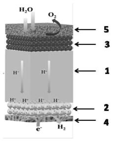
The invention provides a membrane electrode assembly for a solid polymer electrolyte electrolytic cell and a preparation method. The membrane electrode assembly comprises a solid polymer electrolyte membrane, a cathode catalyst coating layer and an anode catalyst coating layer which are arranged on the two sides of the solid polymer electrolyte membrane, and a cathode gas diffusion layer and an anode gas diffusion layer which are arranged on the two sides of the cathode catalyst coating layer and the two sides of the anode catalyst coating layer respectively; the above components are combinedtogether through a certain process to form the membrane electrode assembly. The anode catalyst is a core-shell structure catalyst of which the interior is ruthenium oxide and the exterior is iridium oxide; the anode gas diffusion layer is a porous titanium plate or foamed titanium and contains the core-shell structure catalyst; and the certain process combination is a hot-pressing process formingthe assembly. The membrane electrode assembly provided by the invention can realize low-cost, high-activity and long-life SPE electrolytic cell application.

Description

technical field [0001] The invention belongs to the technical field of hydrogen production by electrolysis of water, and in particular relates to a membrane electrode assembly for an SPE electrolyzer and a preparation method. Background technique [0002] The use of renewable energy to produce hydrogen to convert water into clean hydrogen not only produces high-purity hydrogen (up to 99.999%), it can be directly used by hydrogen fuel cells without secondary purification, and can also reduce the cost of hydrogen production. For large-scale The development of hydrogen fuel cell vehicles has been strongly supported. Solid polymer electrolyte (SPE) electrolysis technology is an emerging water electrolysis technology. SPE electrolyzer has the advantages of compact structure, high current density, high pressure resistance, and high purity of hydrogen production, which has attracted a lot of attention. [0003] In the solid polymer electrolyte electrolyzer structure, the solid pol...

Claims


Application Information

Patent Timeline
Patent Type & Authority Applications(China)
IPC IPC(8): C25B11/06C25B11/03C25B1/10
CPCC25B11/03C25B1/04C25B9/73C25B11/057C25B11/051C25B11/091Y02E60/36
Inventor 吕洪王森周伟张存满沈亚皓
Owner TONGJI UNIV
Learn More