Prosthesis with porous surface structure

A technology with surface structure and porosity, applied in prostheses, medical science, spinal implants, etc., can solve the problems of inability to weld the support and the base support, the strength of the base structure is reduced, and it is weak, and achieves excellent bone ingrowth performance. Effect

Active Publication Date: 2020-06-16
YBNX MEDICAL TECH SUZHOU CO LTD
View PDF7 Cites 0 Cited by
  • Summary
  • Abstract
  • Description
  • Claims
  • Application Information

AI Technical Summary

Problems solved by technology

However, when the porosity of the porous structure is high (>50%), the proportion of interconnected scaffolds is low and weak; a large number of pores are formed between the scaffolds
Whether such a high-porosity structure is realized by metal 3D printing additive manufacturing process or by sintering, when the porous structure and the substrate are directly connected by laser welding, as long as the effective diameter of the laser beam is close to or even larger than the width of the stent , the laser energy may directly break the support structure, break through the porous structure, and cannot achieve welding connection between the porous structure support and the base support
Or, when penetration welding is used to connect the porous structure and the substrate, the strength of the substrate structure will be greatly reduced due to the high temperature and high pressure process conditions

Method used


Image

  • Prosthesis with porous surface structure
  • Prosthesis with porous surface structure
  • Prosthesis with porous surface structure

Examples


Embodiment 1

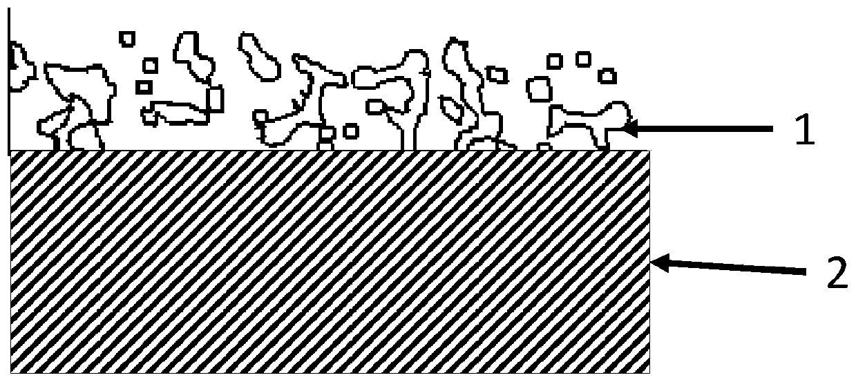
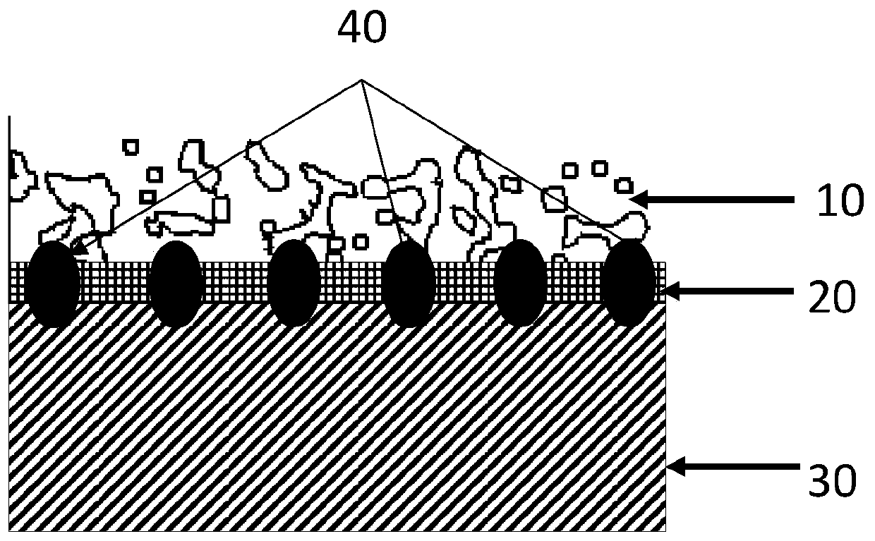
[0154] The present invention relates to a connection structure, such as figure 2 As shown, it includes a substrate 30 , an intermediate body 20 , and a porous surface structure 10 . Wherein, the porous surface structure 10 and the intermediate body 20 form a composite body, and the composite body is connected to the substrate 30 through the connection between the intermediate body 20 and the substrate 30 .

[0155] The preferred substrate 30 is solid, which facilitates the overall strength of the joint structure. The exemplary base 30 is made of metal material, formed by various methods such as forging, casting, powder metallurgy or metal powder injection molding, and various machining processes can be performed on it. The intermediate body 20 and the substrate 30 are preferably effectively combined by welding (such as laser welding), figure 2 The symbol 40 in represents the welding point 40 between the two, and the position of the welding point 40 can be freely selected a...

Embodiment 2

[0167] For the above-mentioned first embodiment, the intermediate body generally includes the bottom (or includes the bottom and the periphery at the same time), and the bottom is roughly in the shape of a thin sheet or a thin plate; the shape and size of an intermediate body (or a combination of multiple intermediate bodies) can be compared with those on the substrate. The shape and size of the connection area of ​​the intermediate body are basically the same; the connection area of ​​the intermediate body and the substrate is welded, so that the porous surface structure forming a complex with the intermediate body covers the connection area of ​​the substrate and constitutes the surface at the connection area.

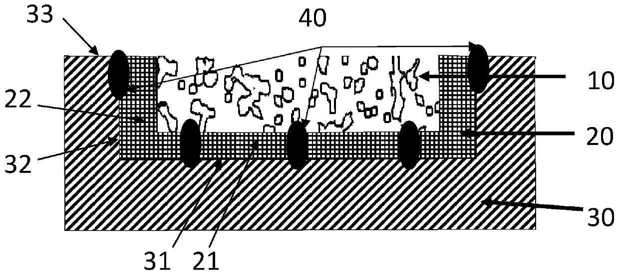
[0168] The main difference from Embodiment 1 is that in the connection structure between the porous surface structure and the substrate described in Embodiment 2, the intermediate between the porous surface structure and the substrate uses an anchor point form, and the...

Embodiment 3

[0175] For the above-mentioned embodiment two, several intermediates in the form of anchor points are independent of each other and form a complex with the porous surface structure; the shape and size of a complex (or after a plurality of complexes are combined) can be connected with the substrate The shape and size of the regions are basically the same; the independent anchor point structure is welded to the corresponding points of the connection region of the substrate, so that the complex covers the connection region of the substrate and forms the surface of the connection region (mainly with a porous surface structure).

[0176] The main difference from Example 2 is that in the connection structure between the porous surface structure and the substrate described in Example 3, the intermediate between the porous surface structure and the substrate uses a joint anchor point structure, that is, it contains multiple Anchor points, and each anchor point is connected to at least ...


PUM


Abstract

The invention provides a prosthesis with a porous surface structure. The porous surface structure and an intermediate are connected in advance to form a complex; the intermediate is connected with a substrate, so that the complex is connected with the substrate, and the porous surface structure can cover the surface of the substrate. Wherein the substrate is of a solid or high-density porous structure; the intermediate is a solid or high-density porous structure, and the density of the intermediate is between the density of the porous surface structure and the density of the substrate. According to the present invention, the prosthesis can be taken as a prosthesis main body of the substrate, processing is convenient, the strength is high, the bone ingrowth performance is optimized throughthe porous surface structure effectively combined with the prosthesis main body, such that the cross section of the prosthesis can be minimized.

Description

technical field [0001] The invention relates to the connection technology of mechanical structures, in particular to medical instruments, and provides a prosthesis with a porous surface structure. Background technique [0002] Engineering applications often have different requirements on the overall performance and surface performance of mechanical structures. For example, the overall performance (such as fatigue strength) of the acetabular cup and femoral stem of the artificial hip joint must meet the dynamic load that the prosthesis bears when it is implanted in the body for decades, with an average of one million to two million walks per year The lower anti-fatigue requirements, and specific performance requirements for the surface of the prosthesis, to meet the firm combination of the surface of the prosthesis and the patient's bone tissue to ensure that the prosthesis does not loosen. Otherwise, the patient will have pain, and the prosthesis must be removed, and the pa...

Claims


Application Information

Patent Timeline
Patent Type & Authority Applications(China)
IPC IPC(8): A61F2/30A61F2/34A61F2/36A61F2/38A61F2/44
CPCA61F2/34A61F2/36A61F2/30942A61F2002/30011A61F2002/3092A61F2002/30985B33Y80/00A61F2002/3093A61F2002/30971A61F2310/00796A61F2002/30014A61C8/00A61F2/32A61F2/38A61F2/40A61F2/42A61F2/44A61F2002/30052A61F2002/30451A61F2002/30967A61F2002/3097A61F2002/30973A61F2/3094A61F2/30767A61C8/0012A61C8/0013Y02E60/50Y02P10/25A61F2/30771A61F2/3662A61F2/3859A61F2/389A61F2002/3006A61F2002/30324A61F2002/30329A61F2002/30772A61F2002/3863B23K11/11B23K11/14B23K11/16
Inventor 姚建清史金虎
Owner YBNX MEDICAL TECH SUZHOU CO LTD
Why Eureka
Try Eureka