Desulfurization liquid cooperated chlorine dioxide gas-phase oxidation denitration integrated flue gas purification device and process

A flue gas purification and desulfurization liquid technology, applied in inorganic chemistry, gas treatment, alkali metal compounds, etc., can solve the problems of loss of denitration effect of desulfurization liquid, high cost of recovered resources, and increase of alkali consumption for denitrification, etc., so as to improve the overall desulfurization Denitrification and dust removal efficiency, reduction of denitration cost and waste liquid discharge, and effect of saving oxidant consumption

Pending Publication Date: 2020-07-14
NANJING UNIV OF SCI & TECH
View PDF12 Cites 10 Cited by
  • Summary
  • Abstract
  • Description
  • Claims
  • Application Information

AI Technical Summary

Problems solved by technology

Although the device is highly integrated, the process is simple, and the floor space is small, there are problems: (1) The desulfurization and oxidation areas are in the same room, and the SO in the flue gas 2 Easy to flow to the oxidation zone, competing with NO to consume ClO 2 Oxidants will not only increase the oxidation cost, but also cause incomplete oxidation of NO, resulting in a decrease in denitrification rate; (2) sharing desulfurization and denitrification spray fluid will make the absorption of 2 The denitration spray liquid oxidizes SO in the desulfurization liquid 2 2- , causing the desulfurization liquid to lose its denitration effect, thereby increasing the amount of alkali used for denitration; (3) There is a partition between the oxidation zone and the denitration zone to increase the system resistance; (4) The design of a single tower should ensure that...

Method used


Image

  • Desulfurization liquid cooperated chlorine dioxide gas-phase oxidation denitration integrated flue gas purification device and process

Examples


Embodiment 1

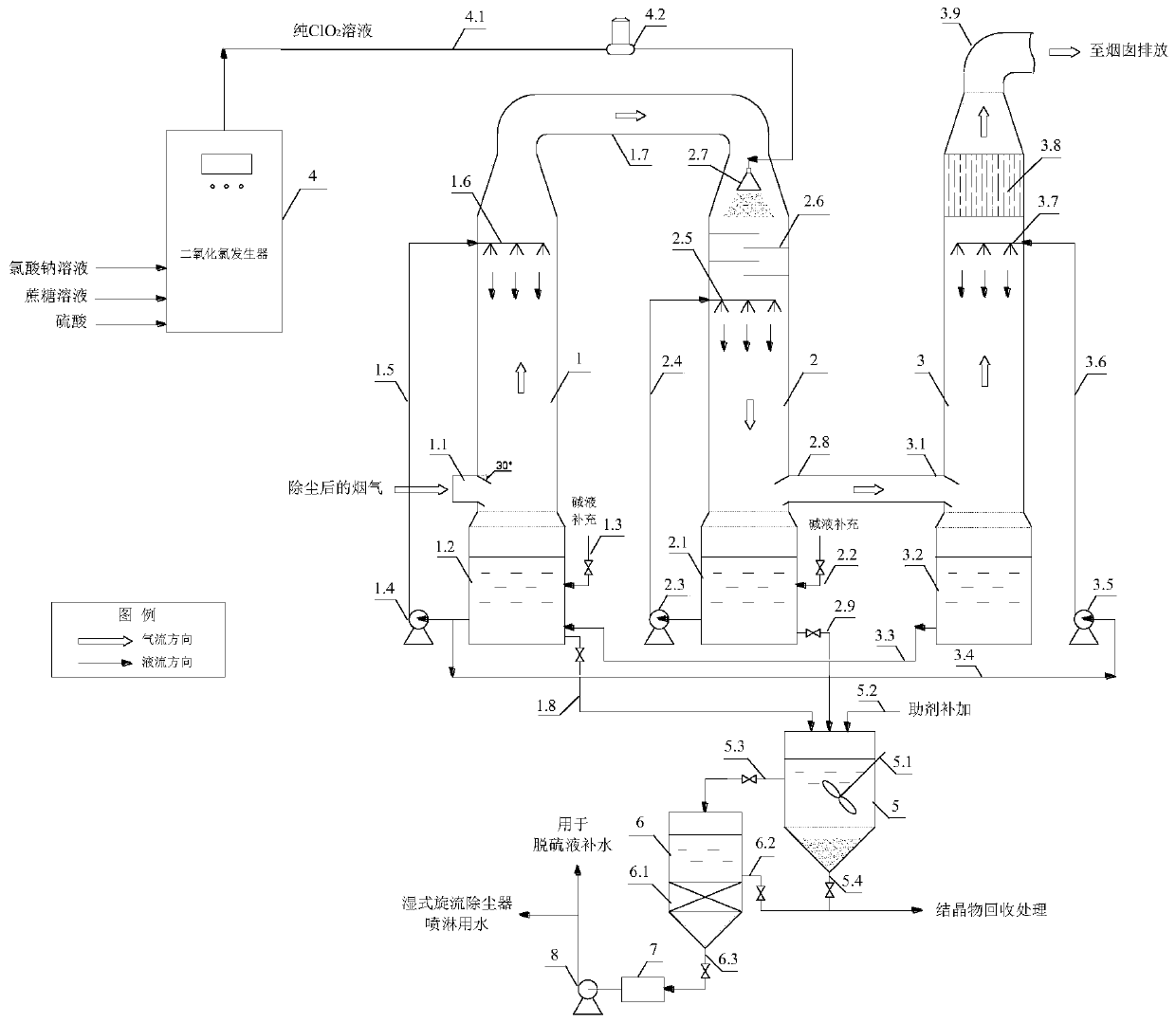
[0056] Using the present invention figure 1 The process shown is to treat the flue gas of a 30t / h heat medium oil chain grate coal-fired boiler. Flue gas flow rate is 64400m 3 / h, particulate matter is 1963~1989mg / m 3 , SO 2 896~913mg / m 3 , NO x 290~320mg / m 3 (NO accounts for about 95%); before the flue gas enters the desulfurization tower, the multi-tube dust collector and the wet cyclone dust collector are used for dust removal.

[0057] The desulfurization agent uses NaOH, the concentration is 0.5mol / L, the pH is maintained at 6-8 during the operation, and the circulation volume of desulfurization liquid is 80m 3 / h (liquid-gas ratio: 1.2L / m 3 ); the denitration agent uses NaOH, the concentration is 0.2mol / L, the pH is maintained at 6-8 during the operation, and the denitrification liquid circulation volume is 50m 3 / h (liquid-gas ratio: 0.8L / m 3 ), ClO 2 The supply rate is 22kg / h (ClO 2 / NO molar ratio: 0.52); the spray liquid of the secondary purification tower ...


PUM


Abstract

The invention provides a desulfurization liquid cooperated chlorine dioxide gas-phase oxidation denitration integrated flue gas purification device and process, a desulfurization tower, an oxidation denitration tower and a secondary purification tower are communicated through a flue, and the flue gas flow direction is in an S-shaped layout. The flue gas subjected to dust removal firstly enters a desulfurizing tower and is desulfurized in an alkali liquor spraying and absorbing manner; the desulfurized flue gas is firstly mixed with ClO2 gas in an oxidation denitration tower to oxidize NO intoNO2, and then denitration is carried out in an alkali liquor spraying absorption mode; and the desulfurized and denitrified flue gas are sprayed and cleaned in the secondary purification tower again by using a desulfurizing solution, residual NOx and SO2 are absorbed in the flue gas, and demisting is performed by using wet electric precipitation to finish final purification. According to the invention, desulfurization, oxidation denitration, secondary purification and waste liquid pretreatment links which are independently arranged and organically combined are utilized to realize effective utilization of desulfurization liquid, ultra-clean treatment of flue gas, recovery of desulfurization and denitration products and reuse of process water, so that the effects of water saving and emissionreduction are achieved while the flue gas is purified.

Description

technical field [0001] The invention relates to the field of desulfurization and denitrification of boiler flue gas, in particular to an integrated flue gas purification device and process of desulfurization liquid in cooperation with chlorine dioxide gas-phase oxidation denitrification. Background technique [0002] SO in boiler flue gas 2 and NO x It is an important precursor substance to form air pollution phenomena such as acid rain or smog. Desulfurization and denitrification treatment of boiler flue gas is the key to control SO 2 , NO x Emissions and an important means to ensure the quality of the atmospheric environment. SO 2 It is easily soluble in water. At present, the lye wet desulfurization technology has been widely used due to its simple process, high efficiency and mature technology. while NO x Due to the insoluble NO in water, the denitrification method is relatively more complicated. Although the commonly used selective catalytic reduction (SCR) denit...

Claims


Application Information

Patent Timeline
IPC IPC(8): B01D53/78B01D53/50B01D53/76B01D53/56B01D53/75C01D9/06C01D5/00
CPCB01D53/502B01D53/56B01D53/75B01D53/76B01D53/78B01D2251/108B01D2251/304B01D2251/604B01D2258/0283C01D5/00C01D9/06
Inventor 李新杰杨钦唐淑娟于文敦
Owner NANJING UNIV OF SCI & TECH
Why Eureka
Try Eureka