Composite coating low-temperature temperature measurement optical fiber and preparation method thereof

A technology of temperature measuring fiber and composite coating, applied in cladding fiber, coating, metal material coating process, etc., can solve the problems of low sensitivity of temperature measuring fiber, decrease of interlayer interface bonding force, etc., and achieve spectral shift Significant, improved temperature sensitivity, excellent interlayer bonding effect

Inactive Publication Date: 2020-07-14
BEIJING JIAOTONG UNIV +1
View PDF3 Cites 1 Cited by
  • Summary
  • Abstract
  • Description
  • Claims
  • Application Information

AI Technical Summary

Problems solved by technology

[0006] In order to overcome the shortcoming of low sensitivity of temperature-measuring optical fiber at low temperature in the quench detection of high-temperature superconducting equipment, and to overcome the high-temperature melting coating process of the metal coating in the preparation process of the current composite coated optical fiber, which is easy to cause the inner polymethyl acrylate coating The shortcoming of the decrease of interlayer interfacial bonding force caused by layer cracking, the invention provides a kind of preparation method of composite coated optical fiber, specifically adopts cold spraying method to coat metal coating on polymethyl acrylate coating surface, can avoid Disadvantages of cracking of polymethyl acrylate coating and deterioration of interfacial bonding force caused by high temperature and long time during metal fusion coating

Method used


Image

  • Composite coating low-temperature temperature measurement optical fiber and preparation method thereof
  • Composite coating low-temperature temperature measurement optical fiber and preparation method thereof
  • Composite coating low-temperature temperature measurement optical fiber and preparation method thereof

Examples


preparation example Construction

[0039] The preparation method of the above-mentioned composite coating temperature measuring optical fiber comprises the following steps:

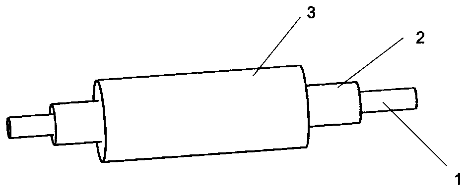
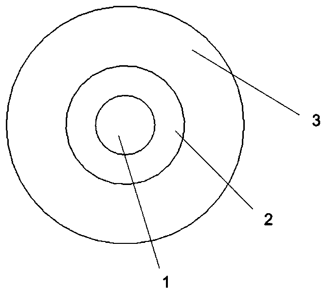
[0040] 1. The acrylic resin is coated on the surface of the bare optical fiber by dip coating-ultraviolet curing process, and after multiple coatings, a polymer coating with a layer thickness of 10 μm to 200 μm is formed on the surface of the bare optical fiber;

[0041]2. Using a cold spraying machine, metal powder (Sn (99.9% weight purity), PbSnAg (62% Sn, 36% Pb and 2% Ag), InBi (66.3% In and 33.7% Ag) with an average particle size of 100nm to 50μm %Bi), SnAg (98.5% Sn and 1.5% Ag) or InSn (69.5% In and 30.5% Sn)), the specific ratio of each metal fluctuates within 2%; after preheating at 60-200 ° C, spray on the polymerization coating surface, spraying gas and powder feeding gas are N 2 , the gas pressure is 0.5~3MPa, and the spraying distance is 10~30cm;

[0042] 3. The optical fiber sprayed with the metal coating is quickly heat-tr...

Embodiment 1

[0045] (1) The acrylic resin is subjected to a dip coating-ultraviolet curing process, and after multiple coatings, a polymer coating with a thickness of about 60 μm is formed on the surface of the bare optical fiber.

[0046] (2) Using a low-pressure cold spraying machine, spray metal tin (Sn) powder with an average particle size of 5 μm on the surface of the polymer coating at 200 ° C, and the spraying gas and powder feeding gas are both N 2 , the gas pressure is 1MPa, the spraying distance is 20cm, and finally a 60μm metal tin coating is formed on the surface of the polymer.

[0047] (3) The optical fiber sprayed with the metal coating is quickly heat-treated in a high-temperature furnace at 235° C. for 50 seconds to form a dense metal coating.

[0048] (4) Place the prepared composite coated temperature-measuring optical fiber at 50° C. for 24 hours before use.

Embodiment 2

[0050] (1) The acrylic resin is dipped and coated-ultraviolet curing process, and after multiple coatings, a polymer coating with a thickness of about 200 μm is formed on the surface of the bare optical fiber.

[0051] (2) Using a low-pressure cold spraying machine, spray metal indium bismuth (InBi) alloy powder with an average particle size of 50 μm on the surface of the polymer coating (2) at 60 ° C, and the spraying gas and powder feeding gas are both N 2 , a gas pressure of 3 MPa, a spraying distance of 30 cm, and finally a 120 μm metal indium bismuth coating is formed on the surface of the polymer.

[0052] (3) The optical fiber sprayed with the metal coating is rapidly heat-treated in a high-temperature furnace at 80° C. for 50 seconds to form a dense metal coating.

[0053] (4) Place the prepared composite coated optical fiber at 50° C. for 24 hours for use.


PUM

PropertyMeasurementUnit
thicknessaaaaaaaaaa
thicknessaaaaaaaaaa
thicknessaaaaaaaaaa

Abstract

The invention relates to a composite coating low-temperature temperature measurement optical fiber and a preparation method thereof. The optical fiber comprises a bare optical fiber, a polymer coatingand a metal coating. The preparation method of the composite coating temperature measurement optical fiber comprises the following steps: 1, coating acrylic resin on the surface of a bare optical fiber by adopting a dip-coating-ultraviolet curing process, and forming a polymer coating on the surface of the bare optical fiber through multiple times of coating; 2, adopting a cold spraying machine,and spraying metal powder to the surface of the polymer coating after being preheated, wherein the spraying gas and the powder feeding gas are both N2; 3, performing rapid heat treatment on the optical fiber sprayed with the metal coating through a high-temperature furnace, and forming a compact metal coating on the surface of the polymer coating; 4, standing the composite coating temperature measurement optical fiber obtained in the step 3 for 24 hours to obtain a finished product. According to the invention, the temperature sensitivity of the temperature measurement optical fiber at low temperature is improved, and the problem that the polymer is easily decomposed at high temperature due to direct contact between molten metal and the polymer in the traditional melt coating process is effectively avoided.

Description

technical field [0001] The invention belongs to the technical field of optical fiber low-temperature measurement and control and superconducting equipment low-temperature testing, and in particular relates to a preparation method of a composite coated temperature-measuring optical fiber. Background technique [0002] Superconducting equipment has the characteristics of low loss and high current carrying capacity, and has attracted extensive attention from the power industry. However, superconducting devices have always faced the risk of quench failure. Due to the thermal effect of the resistance after quenching, the heat in the local area will accumulate rapidly and the temperature will rise. If it cannot be found in time and dealt with accordingly, the thermal effect accumulation will cause the cooling medium in the confined space to boil, the strip will burn, and even lead to more serious problems. risks of. Therefore, monitoring the temperature changes in various places...

Claims


Application Information

Patent Timeline
Patent Type & Authority Applications(China)
IPC IPC(8): G02B6/02G01K11/32C23C24/04C22C28/00C22C13/00
CPCG02B6/02033G02B6/02G01K11/32C23C24/045C22C13/00C22C28/00
Inventor 戴少涛方埼磊张腾莫思铭蔡渊袁文马韬胡磊王邦柱
Owner BEIJING JIAOTONG UNIV
Why Eureka
Try Eureka