Sludge heat treatment recycling process
A sludge and process technology, applied in the field of sludge heat treatment and reuse process, can solve the problems of short development time of hydrothermal carbonization technology, and achieve the effects of increasing SCOD content, developing pores, and improving physical and chemical properties
- Summary
- Abstract
- Description
- Claims
- Application Information
AI Technical Summary
Problems solved by technology
Method used
Image
Examples
Embodiment 1
[0045] A sludge heat treatment and reuse process, comprising the following steps:
[0046] S1, Sludge preheating: Preliminary dehydration is carried out after the sludge is filtered through an 8mm fence. After dehydration, the sludge is continuously introduced into the feeding unit, and the sludge is repeatedly heat-exchanged to 31.5°C by the external filtrate of the feeding unit;
[0047] S2, heat treatment: the preheated sludge enters the heat treatment unit through the feed unit, and the temperature reaches 98°C for heat treatment; the oxygen content in the heat treatment process is 10%; the dust concentration is less than 65mg / m 3 .
[0048] S3, cooling: the heat-treated sludge flows to the cooling zone, and the sludge cooling speed and time are determined according to the properties of the sludge and the requirements for the moisture content of the dewatered sludge;
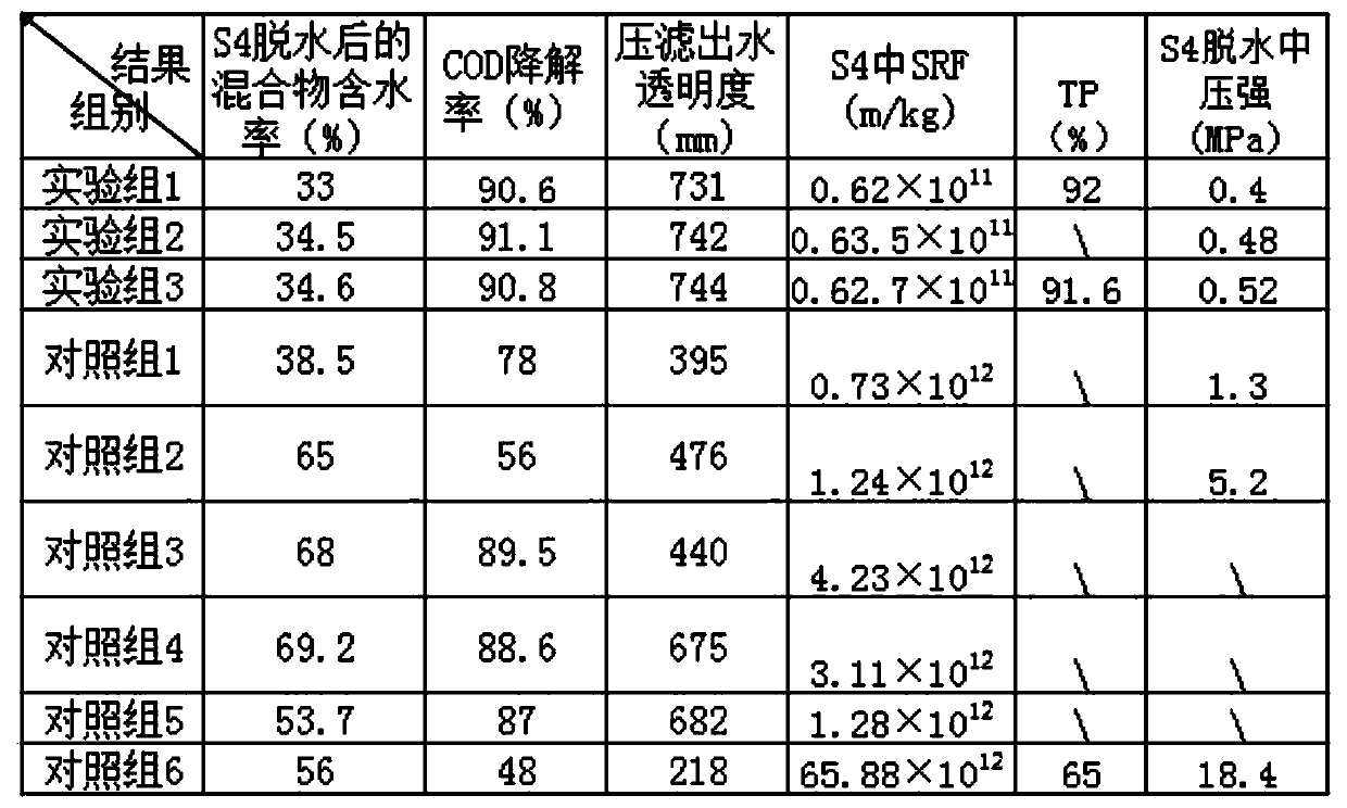
[0049] S4, dehydration: mix the fibrous material with a dehydrating agent, stir the obtained mixture, pr...
Embodiment 2
[0056] A sludge heat treatment and reuse process, comprising the following steps:
[0057] S1, sludge preheating: the sludge is preliminarily dehydrated after being filtered through a 6mm fence. After dehydration, the sludge is continuously introduced into the feeding unit, and the sludge is heated to 30°C by the external filtrate of the feeding unit for many times;
[0058] S2, heat treatment: the preheated sludge enters the heat treatment unit through the feed unit, and the temperature reaches 73°C for heat treatment;
[0059] S3, cooling: the heat-treated sludge flows to the cooling zone, and the sludge cooling speed and time are determined according to the properties of the sludge and the requirements for the moisture content of the dewatered sludge;
[0060] S4, dehydration: mixing the fibrous material with a dehydrating agent, stirring the obtained mixture, and dehydrating by pressing until the moisture content of the mixture is reduced to 34% by weight;
[0061] S5, co...
Embodiment 3
[0067] A sludge heat treatment and reuse process, comprising the following steps:
[0068] S1, sludge preheating: the sludge is preliminarily dehydrated after being filtered through a 10mm fence. After dehydration, the sludge is continuously introduced into the feeding unit, and the sludge is heated to 60°C by the external filtrate of the feeding unit for many times;
[0069] S2, heat treatment: the preheated sludge enters the heat treatment unit through the feed unit, and the temperature reaches 174°C for heat treatment; the oxygen content in the heat treatment process is 12%; the dust concentration is 67.8mg / m3.
[0070] S3, cooling: the heat-treated sludge flows to the cooling zone, and the sludge cooling speed and time are determined according to the properties of the sludge and the requirements for the moisture content of the dewatered sludge;
[0071] S4, dehydration: mix the fibrous material with a dehydrating agent, stir the obtained mixture, press and dehydrate until ...
PUM
| Property | Measurement | Unit |
|---|---|---|
| diameter | aaaaa | aaaaa |
| length | aaaaa | aaaaa |
| diameter | aaaaa | aaaaa |
Abstract
Description
Claims
Application Information
 - R&D
- Intellectual Property
- Life Sciences
- Materials
- Tech Scout
- Unparalleled Data Quality
- Higher Quality Content
- 60% Fewer Hallucinations
Browse by: Latest US Patents, China's latest patents, Technical Efficacy Thesaurus, Application Domain, Technology Topic, Popular Technical Reports.
© 2025 PatSnap. All rights reserved.Legal|Privacy policy|Modern Slavery Act Transparency Statement|Sitemap|About US| Contact US: help@patsnap.com

