SNCR denitration system and method for removing escaping ammonia in SNCR denitration process

A ammonia escape and denitrification technology, applied in separation methods, chemical instruments and methods, gas treatment, etc., can solve the problems of small processing capacity, removal of trace ammonia with difficult ppm content, no ammonia escape removal, etc., achieving low cost, Effects with obvious effects and important application value

Inactive Publication Date: 2020-08-18
NANJING WEIHENG EXPERIMENTAL EQUIP CO LTD
View PDF9 Cites 4 Cited by
  • Summary
  • Abstract
  • Description
  • Claims
  • Application Information

AI Technical Summary

Problems solved by technology

These technologies are all based on the removal of ammonia in the gas under low temperature conditions, and all need to establish an independent system. The small processing capacity is difficult to achieve the removal of trace amounts of ammonia in ppm, and there is no removal of ammonia escape in the SNCR process.

Method used


Image

  • SNCR denitration system and method for removing escaping ammonia in SNCR denitration process
  • SNCR denitration system and method for removing escaping ammonia in SNCR denitration process
  • SNCR denitration system and method for removing escaping ammonia in SNCR denitration process

Examples


Embodiment 1

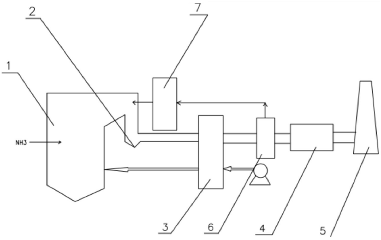
[0035] A SNCR denitrification system, such as figure 1 As shown, it includes denitration reaction zone 1, economizer 2, air preheater 3, dust collector 6, desulfurization tower 4 and chimney 5, denitration reactor, economizer 2, air preheater 3, dust collector 6, The connection mode between the desulfurization tower 4 and the chimney 5 is well known to those skilled in the art, and will not be repeated here.

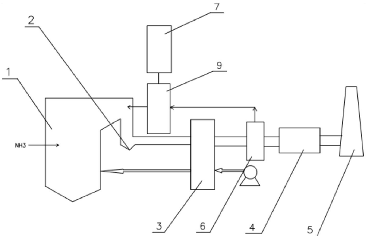
[0036] The SNCR denitrification system also includes a pneumatic conveying device 9 and an ammonia conversion catalyst supply device 7 .

[0037] The ammonia conversion catalyst supply device 7 is connected to the gas outlet flue of the denitration reactor through a pneumatic conveying device 9, and the pneumatic conveying device 9 is arranged between the economizer 2 and the denitration reactor.

[0038] The dust outlet of the dust remover 6 is connected with the feed inlet of the ammonia conversion catalyst supply device 7 .

[0039] The pneumatic conveying device 9 in...

Embodiment 2

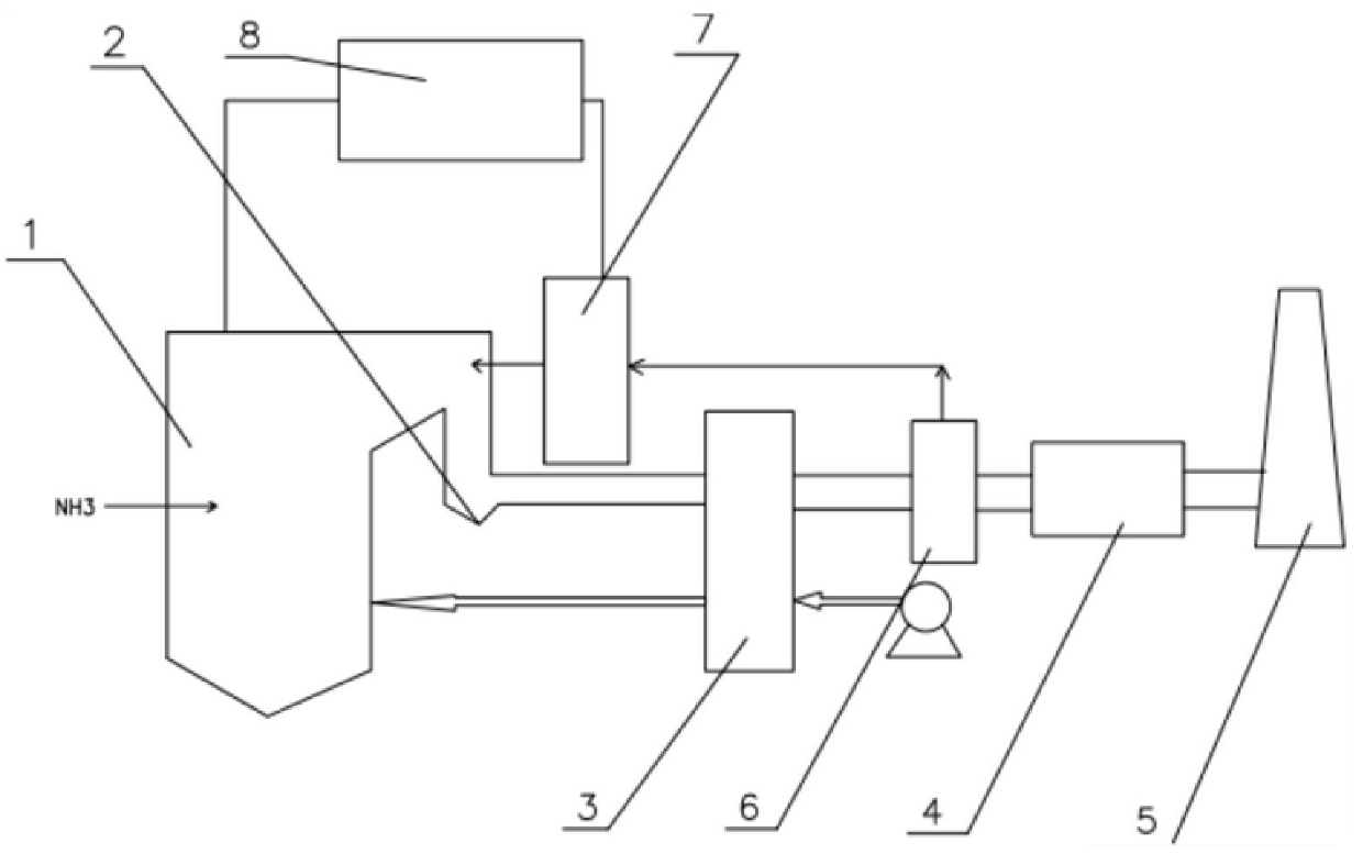
[0042] An SNCR denitrification system, comprising a denitrification reaction zone 1, an economizer 2, an air preheater 3, a dust collector 6, a desulfurization tower 4 and a chimney 5, a denitrification reactor, an economizer 2, an air preheater 3, and a dust collector The connection mode between device 6, desulfurization tower 4 and chimney 5 is known to those skilled in the art, and will not be repeated here;

[0043] The SNCR denitrification system also includes a pneumatic mixing device 8 and an ammonia conversion catalyst supply device 7;

[0044] The pneumatic mixing device 8 is connected to the ammonia conversion catalyst supply device 7 and the gas outlet flue of the denitration reactor respectively, and the pneumatic mixing device 8 is arranged between the denitration reactor and the economizer 2;

[0045] The air inlet of the dust remover 6 is connected with the air outlet of the pneumatic mixing device 8, and the dust outlet of the dust remover 6 is connected with t...

Embodiment 3

[0049] The flue gas treated by the SNCR denitrification system described in Example 1 is the flue gas of a certain waste incineration power generation, with a flue gas volume of 50,000 Nm³ / h. The powder is entrained into the flue and mixed with the flue gas. The amount of new catalyst added is 0.1kg / Nm³ (5kg / h), the circulating catalyst is 100kg / h, and the NOx concentration in the flue gas is reduced from 100mg / Nm³ to 60mg / Nm³; the outlet ammonia concentration Reduced from 50mg / Nm³ to 5mg / Nm³, the amount of ammonia escape is less than 3ppm, and the emission of flue gas meets the latest European standards.


PUM

PropertyMeasurementUnit
particle diameteraaaaaaaaaa

Abstract

The invention discloses a method for removing escaping ammonia in an SNCR denitration system. The ammonia oxidative degradation system comprises an SNCR denitration system which consists of a deamination reaction zone, a coal economizer, an air preheater, a desulfurizing tower and a chimney, and further comprises a pneumatic mixing device or a pneumatic conveying device and an ammonia conversion catalyst supply device, wherein the pneumatic mixing device is respectively connected with the ammonia conversion catalyst supply device and a gas outlet flue of the deamination reaction zone; and theammonia conversion catalyst supply device is connected with gas outlet flues of the boiler economizer and the dust remover through the pneumatic conveying device. The method comprises the following steps: pneumatically mixing flue gas generated in a denitration reaction zone of the SNCR denitration system with an ammonia conversion catalyst at 300-700 DEG C, and carrying out catalytic oxidation reaction on ammonia to obtain ammonia-removed flue gas. According to the system and the method, escape of ammonia in the flue gas can be eliminated, the NO concentration in the flue gas can be further reduced, secondary pollution to the environment is avoided, and the system and the method are important supplements for a traditional SNCR process, are low in equipment investment and have important application values.

Description

technical field [0001] The invention relates to the technical field of environmental protection, in particular to an SNCR denitration system and a method for removing escaped ammonia in the SNCR denitration process. Background technique [0002] In view of the large amount of cement, garbage incineration, hazardous waste incineration and small and medium-sized industrial combustion furnaces in China, we currently mainly use ammonia selective reduction (selective non-catalytic reduction SNCR and selective catalytic reduction technology SCR) to reduce nitrogen in flue gas. The oxide is removed, and the chemical reaction formula is as follows: [0003] 4NH 3 +4NO+O 2 =4N 2 +6H 2 O; [0004] Among them, the SNCR process usually reacts at around 900°C. Due to the absence of a catalyst, the reaction rate is slow and the NOx conversion rate is relatively low; while the SCR reaction is usually carried out at 200-500°C in the presence of a catalyst. catalytic reduction reaction...

Claims


Application Information

Patent Timeline
Patent Type & Authority Applications(China)
IPC IPC(8): B01D53/86B01D53/58B01D53/56
CPCB01D53/8634B01D53/58B01D53/56B01D2257/404B01D2258/0283B01D2257/60B01D2255/20738B01D2255/20746B01D2255/20753B01D2255/2092B01D2255/2073B01D2255/20707B01D2255/30
Inventor 余剑
Owner NANJING WEIHENG EXPERIMENTAL EQUIP CO LTD
Why Eureka
Try Eureka