Laser millimeter wave integrated ranging and speed measuring radar method and device

A speed measuring radar, millimeter wave technology, applied in measurement devices, radio wave measurement systems, electromagnetic wave re-radiation and other directions, can solve problems such as reducing system robustness, bias drift, etc.

Inactive Publication Date: 2020-09-22
孙建锋
View PDF0 Cites 18 Cited by
  • Summary
  • Abstract
  • Description
  • Claims
  • Application Information

AI Technical Summary

Problems solved by technology

However, DPMZM has the problem of DC bias drift, which reduces the robustness of the system

Method used


Image

  • Laser millimeter wave integrated ranging and speed measuring radar method and device
  • Laser millimeter wave integrated ranging and speed measuring radar method and device
  • Laser millimeter wave integrated ranging and speed measuring radar method and device

Examples


Embodiment 1

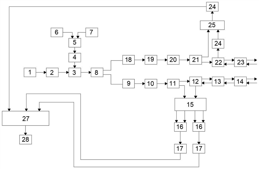
[0089] Example 1: The optical signal generated by the narrow-linewidth single-frequency continuous laser in the radar platform passes through the phase modulator, and the FM signal generated by the FM signal generator and the base frequency signal generated by the base frequency signal generator are obtained after mixing, filtering and amplifying The frequency mixing signal is used as the RF drive signal of the phase modulator to phase modulate the optical signal, and the modulated optical signal is divided into two beams by the first beam splitter, and enters the laser radar channel and the millimeter wave radar channel respectively; In the laser radar channel, the modulated optical signal is band-pass filtered to generate a broadband linear frequency-modulated laser signal, and then amplified, and then divided into a laser local oscillator signal and a laser emission signal by the second beam splitter, and the laser emission signal is transmitted to the target And receive the...

Embodiment 2

[0094] Embodiment 2: a kind of laser millimeter-wave integrated ranging and speed measuring radar method, such as figure 1 As shown, an eye-safe 1550.148nm (corresponding frequency is 193397.0GHz) single-mode narrow-linewidth fiber laser 1 is used, the laser linewidth is 10kHz, the output power is 20mW, and the optical fiber output has isolation protection. The CW laser first passes through the polarizer 2 to ensure that the polarization extinction ratio is greater than 25dB, and the optical signal is expressed as:

[0095] E. 0 (t)=E 0 exp[j2πf 0 t+jφ 0 ];

[0096] In the formula, E 0 is the optical signal amplitude; exp is an exponential function with the natural constant e as the base; f 0 is the laser frequency; t is the time; φ 0 is the initial phase of the optical signal;

[0097] The FM signal produced by the FM signal generator 6 and the base frequency signal produced by the base frequency signal generator 7 are mixed by the radio frequency mixer 5, and then ...


PUM


Abstract

The invention discloses a laser millimeter wave integrated ranging and speed measuring radar method. Modulated optical signals are filtered to generate broadband linear frequency modulation laser signals and broadband linear frequency modulation millimeter wave signals in two channels respectively. The laser signals are divided into laser local oscillation signals and laser emission signals, the laser emission signals are emitted, laser echo signals are received, coherent light mixing is carried out on the laser echo signals and the laser local oscillation signals, and laser channel ranging and speed measuring data are obtained through filtering, analog-to-digital conversion and Fourier transform; the millimeter wave signals are divided into millimeter wave local oscillation signals and millimeter wave emission signals, the millimeter wave emission signals are emitted, millimeter wave echo signal are received, frequency mixing coherent reception is performed on the millimeter wave echosignals and the millimeter wave local oscillator signals, and Fourier transform is used to obtain millimeter wave channel ranging and speed measuring data. Finally, the data of the two channels are fused. According to the invention, the structure is compact, the compatibility is higher, more complex environment can be adapted to, the sweep frequency bandwidth and the repetition frequency can be greatly improved, and bandwidth setting is freer.

Description

technical field [0001] The invention relates to the technical field of laser radar, in particular to a laser millimeter wave integrated ranging and speed measuring radar method and device. Background technique [0002] With the increasingly complex detection environment and the diversified development of detection targets, it is an inevitable trend in the development of radar technology to realize multi-sensor fusion. Multi-sensor fusion is to gather the data and information acquired by various sensors together for comprehensive analysis, so as to describe the external environment more accurately and reliably, thereby improving the correctness of system decision-making. On the one hand, any single detection system has its own limitations and cannot well adapt to the complex work requirements in the future. For example, laser radar, laser radar has the advantages of good directionality, narrow beam, high accuracy of distance measurement, speed measurement and angle measureme...

Claims


Application Information

Patent Timeline
Patent Type & Authority Applications(China)
IPC IPC(8): G01S13/87G01S17/88
CPCG01S13/87G01S17/88
Inventor 职亚楠孙建锋潘卫清戴恩文
Owner 孙建锋
Why Eureka
Try Eureka