
Slow-release modification method of solid electrolyte/metal lithium interface and solid-state lithium metal battery

A technology of solid electrolyte and metal lithium, which is applied in the direction of solid electrolyte, electrolyte storage battery manufacturing, non-aqueous electrolyte storage battery, etc., can solve the problems of no practical value, low lithium ion conductivity, affecting charge and discharge performance, etc., to improve capacity stability And the effects of cycle stability, high Li-ion transport capacity, and ease of large-scale application

Active Publication Date: 2020-11-06
SHANGHAI INST OF CERAMIC CHEM & TECH CHINESE ACAD OF SCI
View PDF10 Cites 4 Cited by
  • Summary
  • Abstract
  • Description
  • Claims
  • Application Information

AI Technical Summary

Problems solved by technology

The second point is that the protective layer must have good lithium ion transmission performance, otherwise the lithium will not be released, and the assembled full battery cannot be cycled, which has no practical value
However, the disadvantages of the above two commonly used (mainstream) methods are: first, the use of molecular deposition equipment and electroplating cannot achieve large-scale production, the cost is high, and it is an ex-situ reaction. Lithium metal is easily squeezed when the battery is assembled in the later stage. etc., the protective layer on its surface is likely to be damaged; secondly, the polymer is used as an intermediate layer for coating, and the lithium ion conductivity of the polymer is very low, resulting in a high overall impedance of the battery after the protective layer is introduced, which in turn affects its charge and discharge. performance

Method used


Image

  • Slow-release modification method of solid electrolyte/metal lithium interface and solid-state lithium metal battery
  • Slow-release modification method of solid electrolyte/metal lithium interface and solid-state lithium metal battery
  • Slow-release modification method of solid electrolyte/metal lithium interface and solid-state lithium metal battery

Examples


Embodiment 1

[0066] Step (1): Polypropylene carbonate and lithium bistrifluoromethanesulfonimide were added into acetonitrile solvent at a mass ratio of 6:1 and stirred until completely dissolved, and prepared to obtain a solution with a concentration of 30 wt%. 40 μL of the above solution was uniformly coated on a metal lithium disc (14 mm in diameter) and dried in vacuum to obtain a lithium metal negative electrode with a self-degradable polymer protective layer on the surface.

[0067] Step (2): Activate the lithium metal negative electrode at 60°C until the polymer layer on its surface presents a viscous gel-like shape, and attach it to the cold-pressed silver-argentite-type sulfide Li 6 P.S. 5 Cl solid electrolyte sheet (disk with a diameter of 14mm) on one side, and then cooled naturally.

[0068] Step (3): In the argentite-type sulfide Li 6 P.S. 5 The other side of the Cl solid electrolyte sheet also carries out the operations of step (1) and step (2). Finally, steel sheets (dis...

Embodiment 2

[0071] It is basically the same as Example 1, the only difference is:

[0072] Step (1): Polypropylene carbonate and lithium bistrifluoromethanesulfonimide were added into acetonitrile solvent at a mass ratio of 6:1 and stirred until completely dissolved, and a solution with a concentration of 40 wt% was prepared. 40 μL of the above solution was uniformly coated on a metal lithium disc (14 mm in diameter) and dried in vacuum to obtain a lithium metal negative electrode with a self-degradable polymer protective layer on the surface.

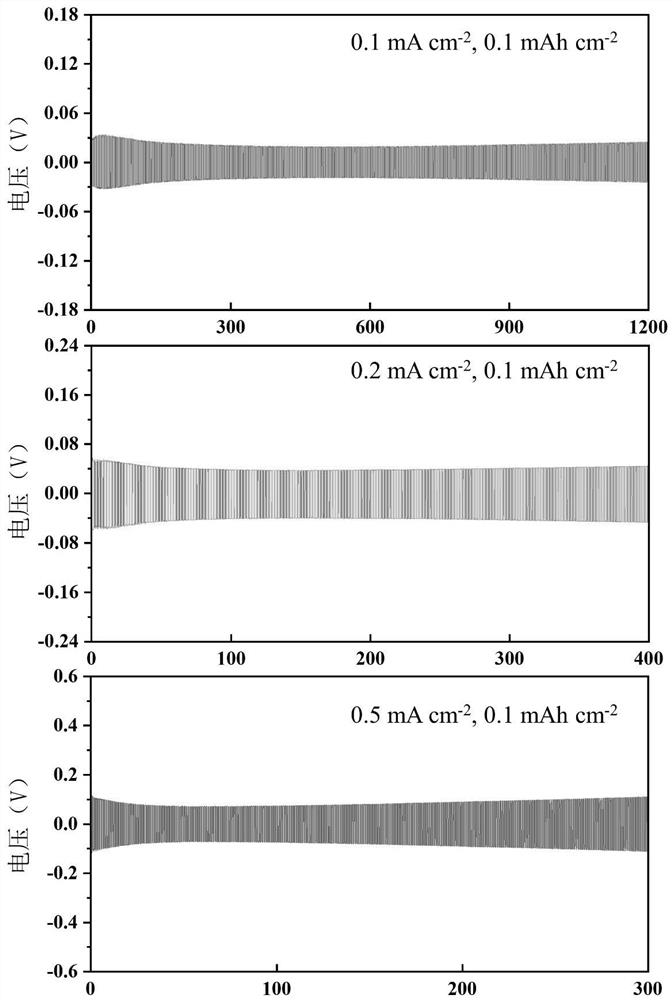
[0073] Battery performance evaluation: Conduct potentiostatic electrochemical AC impedance spectroscopy tests on lithium symmetrical batteries at 25°C, with frequencies ranging from 0.1Hz to 1MHz, such as image 3 As shown, the interface impedance is about 97ohm / cm 2 . The slow-release polarization of the symmetric battery decreases in the early stage during the cycle, and then the polarization is stable, and its interface stability is generally...

Embodiment 3

[0075] It is basically the same as Example 1, the only difference is:

[0076] Step (1): Polypropylene carbonate and lithium bistrifluoromethanesulfonimide were added into the acetonitrile solvent at a mass ratio of 6:1 and stirred until completely dissolved, and a solution with a concentration of 50 wt% was prepared. 40 μL of the above solution was uniformly coated on a metal lithium disc (14 mm in diameter) and dried in vacuum to obtain a lithium metal negative electrode with a self-degradable polymer protective layer on the surface.

[0077]Battery performance evaluation: Conduct potentiostatic electrochemical AC impedance spectroscopy tests on lithium symmetric batteries at 25°C, with frequencies ranging from 0.1Hz to 1MHz, and the interface impedance is about 95ohm / cm 2 . The slow-release polarization of the symmetric battery decreases in the early stage during the cycle, and then the polarization is stable, and its interface stability is generally better.


PUM

PropertyMeasurementUnit
thicknessaaaaaaaaaa
diameteraaaaaaaaaa

Abstract

The invention discloses a slow-release modification method of a solid electrolyte / metal lithium interface and a solid lithium metal battery. The slow-release modification method comprises the following steps: coating the surface of a lithium metal anode with a solution containing a self-degradable polymer and an active substance, and performing drying to form a precursor protection layer on the surface of the lithium metal anode; activating the metal lithium anode with the precursor protection layer on the surface at 40-80 DEG C until the polymer is attached to the surface of the metal lithiumanode in a gel state; assembling a metal lithium electrode with a gel-state precursor protection layer on at least one side of the solid electrolyte to form a solid-state battery, wherein the precursor protection layer releases the loaded active substance in the charge-discharge cycle of the solid-state battery to react with the lithium metal to induce the surface of the lithium metal negative electrode to construct a stable interface protection layer in situ.

Description

technical field [0001] The invention belongs to the field of solid-state lithium metal batteries, and in particular relates to a slow-release modification method of a solid electrolyte / metal lithium interface and a solid-state lithium metal battery. Background technique [0002] Solid-state lithium metal batteries have attracted extensive attention due to their high energy density and high safety, which is due to the high theoretical capacity (3860mAh / g), low reduction potential (-3.04V) and low density of lithium metal. (0.53g / cm -3 ), its high safety is due to the fact that solid-state lithium metal batteries use inorganic solid electrolytes instead of traditional electrolytes to avoid the danger of leakage, evaporation, and combustion. In addition, solid electrolytes have good mechanical strength, which can inhibit the growth of lithium dendrites. Therefore, the commercial application of solid-state lithium metal batteries has broad prospects. [0003] However, some pr...

Claims


Application Information

Patent Timeline
Patent Type & Authority Applications(China)
IPC IPC(8): H01M10/058H01M10/052H01M10/0525
CPCH01M10/058H01M10/052H01M10/0525H01M2300/0065Y02E60/10Y02P70/50
Inventor 温兆银陈亚靳俊
Owner SHANGHAI INST OF CERAMIC CHEM & TECH CHINESE ACAD OF SCI
Learn More