

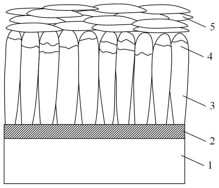
EB-PVD/APS composite structure double-ceramic-layer thermal barrier coating and preparation method thereof
An EB-PVD, composite structure technology, applied in coating, metal material coating process, ion implantation plating and other directions, can solve the problem of unfavorable thick thermal barrier coating, EB-PVD coating preparation process is many, EB-PVD The problem of low coating deposition rate, etc., can prolong the overall protection effect, improve the interface matching, and enhance the anti-peeling ability.
- Summary
- Abstract
- Description
- Claims
- Application Information
AI Technical Summary
Problems solved by technology
Method used
Image

Examples
Embodiment 1
[0032] Embodiment 1: A kind of EB-PVD / APS composite structure double ceramic layer thermal barrier coating (recorded as EB-PVD / APS~1), its specific implementation steps are as follows:
[0033] Step 1: Pretreatment of the substrate surface:
[0034] The substrate of the superalloy sample was wet blasted, and then ultrasonically cleaned with an anhydrous ethanol cleaning agent. The wet sandblasting process is as follows: the sandblasting medium is 100 mesh white corundum, the sandblasting pressure is 0.15MPa, and the sandblasting distance is 70mm.
[0035] Step 2: Preparation of MCrAlY metal bonding layer by electron beam physical vapor deposition
[0036] The treated superalloy sample is clamped in a special tooling, and the MCrAlY metal bonding layer is deposited in the vacuum chamber of the EB-PVD equipment. The vacuum chamber pressure during the deposition process is less than 1.0×10 ~2 Pa, the electron gun voltage is 18~20kV, the MCrAlY target heating current is 1~1.5A, ...
Embodiment 2
[0049] Embodiment 2: A kind of EB-PVD / APS composite structure double ceramic layer thermal barrier coating (recorded as EB-PVD / APS~2), its specific implementation steps are as follows:
[0050] Step 1: Pretreatment of the substrate surface:
[0051] The superalloy sample substrate is subjected to wet sandblasting, and then ultrasonically cleaned with absolute ethanol or cleaning agent. The wet sandblasting process is as follows: the sandblasting medium is 200 mesh white corundum, the sandblasting pressure is 0.4MPa, and the sandblasting distance is 100mm.
[0052] Step 2: Preparation of MCrAlY metal bonding layer by electron beam physical vapor deposition
[0053] The treated superalloy sample is clamped in a special tooling, and the MCrAlY metal bonding layer is deposited in the vacuum chamber of the EB-PVD equipment. The vacuum chamber pressure during the deposition process is less than 1.0×10 ~2 Pa, the electron gun voltage is 18-20kV, the MCrAlY target heating current is...
Embodiment 3
[0067] The difference between this example and Example 1 is that the MCrAlY metal bonding layer is prepared by vacuum arc ion plating in step 2. When vacuum arc ion plating is used to prepare the metal bonding layer, the vacuum chamber pressure is less than 0.3Pa, and the arc current is 80A. The workpiece bias voltage is -25V, and the workpiece heating temperature is 350°C. The obtained composite structure double ceramic layer thermal barrier coating is denoted as EB-PVD / APS~3.
PUM
| Property | Measurement | Unit |
|---|---|---|
| thickness | aaaaa | aaaaa |
| thickness | aaaaa | aaaaa |
| thickness | aaaaa | aaaaa |
Abstract
Description
Claims
Application Information