Optical coherence tomography system for burnt skin

An optical coherence tomography and imaging system technology, applied in the field of optical coherence tomography, can solve the problems of rough two-dimensional image information, low resolution, high cost and technical difficulty, etc., achieve good blood flow sensitivity, and the system is simple and compact , the effect of supporting clinical diagnosis

Active Publication Date: 2021-01-05
FOSHAN UNIVERSITY
View PDF13 Cites 5 Cited by
  • Summary
  • Abstract
  • Description
  • Claims
  • Application Information

AI Technical Summary

Problems solved by technology

[0018] At present, the "gold standard" of burn diagnosis is still histopathological biopsy, but it cannot be practically applied in clinical practice for the following reasons: 1. Biopsy is invasive to the body , the patient may not be able to accept it; 2. Histopathological changes in burns are dynamic and continuous within a certain period of time, and it may not be possible to accurately predict the result for a single biopsy in the early stage to assess the degree of injury; 3. An experienced doctor is required. However, if relying on limited experience medical staff for initial visual diagnosis, the accuracy of judging the burn area and burn degree is only 60% and 51% respectively. A very subjective, low-accuracy skin diagnosis system with huge learning costs and huge risks for doctors and patients
Fluorescence detection technology requires intravenous injection of fluorescent substances; infrared imaging technology requires

Method used


Image

  • Optical coherence tomography system for burnt skin
  • Optical coherence tomography system for burnt skin
  • Optical coherence tomography system for burnt skin

Examples


Embodiment Construction

[0037] The idea, specific structure and technical effects of the present invention will be clearly and completely described below in conjunction with the embodiments and accompanying drawings, so as to fully understand the purpose, scheme and effect of the present invention. It should be noted that, in the case of no conflict, the embodiments in the present application and the features in the embodiments can be combined with each other.

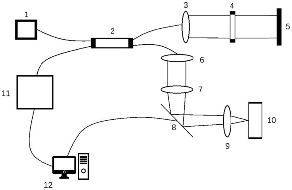
[0038] figure 1 Shown is a structural diagram of an optical coherence tomography system for burned skin, combined below figure 1 A system according to an embodiment of the present invention will be described.

[0039] The present invention proposes an optical coherence tomography system for burned skin, specifically comprising: a light source (1), an optical fiber coupler (2), collimating lenses (3 and 6), and the first collimating lens is a collimating lens (3), the second collimating lens is a collimating lens (6), a dispersion compensati...


PUM

PropertyMeasurementUnit
Center wavelengthaaaaaaaaaa
Bandwidthaaaaaaaaaa

Abstract

The invention discloses an optical coherence tomography system for burnt skin. The optical coherence tomography system comprises an optical coherence tomography instrument and a computer control system, wherein the optical coherence tomography instrument acquires an interference signal of necrotic tissue of burnt skin in a target area, and the computer control system analyzes and processes the interference signal, and burn depth and the burn area of the target area are obtained, the three-dimensional image of the target area is synthesized and displayed, spectral interpolation or calibration is not needed in data processing, and the method is simpler and more efficient; at a sample arm, flexible optical focusing is achieved through a zoom lens; and a dispersion compensation lens is added to a reference arm to compensate optical path dispersion and improve axial resolution, so that dispersion compensation is not needed in data processing, and the method is simpler and more efficient, and interference signals of a wave number space can be acquired in a high-fidelity mode in signal acquisition.

Description

technical field [0001] The invention relates to the field of optical coherence tomography, in particular to an optical coherence tomography system for burned skin. Background technique [0002] Optical coherence tomography (OCT) is an emerging non-invasive optical detection technology that can provide high-resolution three-dimensional images of skin tissue in the field of burn skin diagnosis. The basic structure of OCT is a low-coherence interferometer, that is, the broadband light source is divided into two parts: reference light and sample light. When the coherence length of the light source is changed, optical interference occurs, thereby obtaining an optical interference image. The coherence length of the light source used in the OCT system is usually very small, about 10 μm, so it can provide high-resolution biological tissue information. OCT imaging techniques can be broadly classified into two types: time domain OCT (TDOCT) and Fourier domain OCT (FDOCT). Time-doma...

Claims


Application Information

Patent Timeline
IPC IPC(8): A61B5/00A61B5/026
CPCA61B5/0066A61B5/0073A61B5/445A61B5/7257A61B5/0261
Inventor 许景江韦赢兆袁钘安林黄燕平谭海曙阳娅秦嘉蓝公仆别佳奇
Owner FOSHAN UNIVERSITY
Why Eureka
Try Eureka