A sludge pyrolysis gasification system

A technology of pyrolysis gasification and sludge, which is applied in the direction of gasification process, pyrolysis treatment sludge, granular/powdered fuel gasification, etc. High viscosity of mud and other problems to achieve the effect of improving the use efficiency and effect

Active Publication Date: 2022-05-17
CHONGQING UNIVERSITY OF SCIENCE AND TECHNOLOGY
View PDF19 Cites 0 Cited by
  • Summary
  • Abstract
  • Description
  • Claims
  • Application Information

AI Technical Summary

Problems solved by technology

In addition, sludge contains a large amount of nitrogen, and direct incineration treatment tends to produce higher concentrations of nitrogen oxides, and the organic components in sludge cannot be effectively recovered
Traditional dryers, such as the sludge fluidized bed drying device in CN201410437609.5, use a grinding bed, a return bed and a drying bed to dry the sludge, and it is necessary to add abrasives to prevent the sludge from drying and agglomerating ; The circulating fluidized bed integrated sludge incineration system in CN 110748894A adopts an incinerator and a drier to dry and incinerate the sludge. The above-mentioned drier mostly uses a fluidized bed drier, because the wet sludge has Higher viscosity may easily cause loss of fluidity and affect drying effect
Due to the indirect contact with the sludge of the paddle type dryer, the sludge drying effect is poor

Method used


Image

  • A sludge pyrolysis gasification system
  • A sludge pyrolysis gasification system

Examples


Embodiment Construction

[0028] Embodiments of the present invention will be described in further detail below in conjunction with the accompanying drawings.

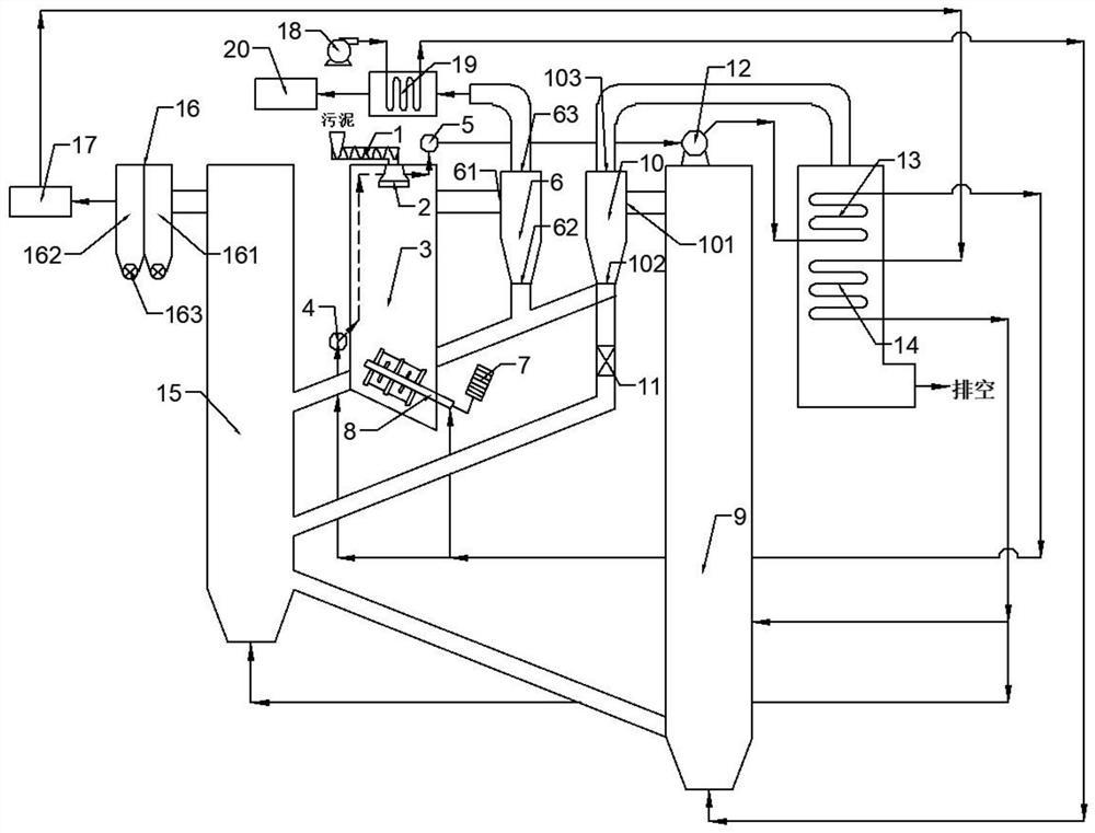
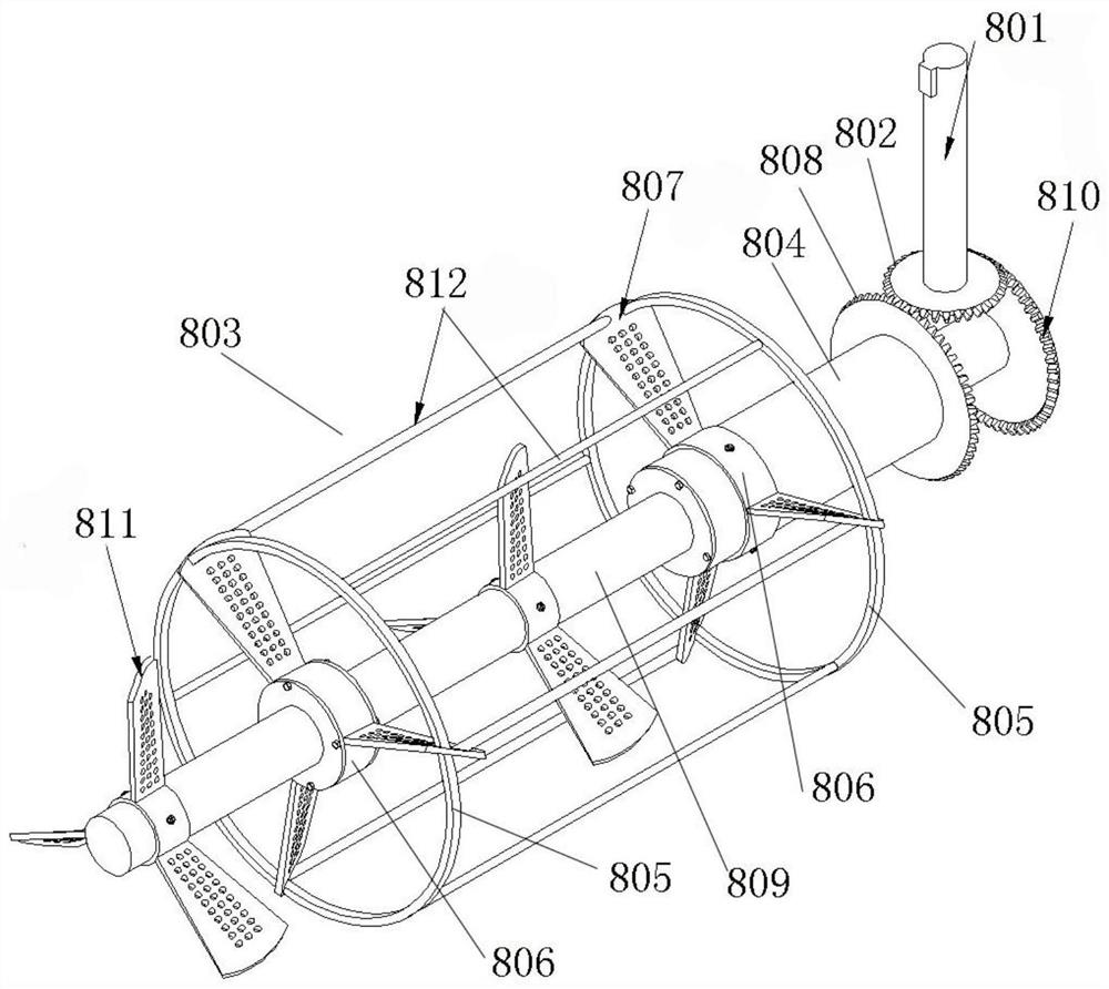
[0029] Such as figure 1 , figure 2As shown, a sludge pyrolysis gasification system includes a sludge thermal drying chamber 3 for thermally drying the sludge. The inner wall of the sludge thermal drying chamber 3 is provided with a steam pipe, The thermal radiation of the superheated steam in the steam pipeline dries the sludge through indirect contact with exothermic heat. A screw feeder 1 is arranged above the sludge thermal drying chamber 3, and a nozzle 2 is also arranged on the top of the sludge thermal drying chamber 3. , connected to the bottom of the screw feeder 1, the raw sludge enters the nozzle 2 through the screw feeder 1, the side and bottom of the nozzle 2 are provided with a number of small holes with a diameter of 8-10mm, and the screw feeder 1 is input The sludge is granulated into small particles by high-speed rotation and...


PUM

PropertyMeasurementUnit
diameteraaaaaaaaaa
diameteraaaaaaaaaa

Abstract

The invention discloses a sludge pyrolysis gasification system, which comprises a screw feeder, a nozzle, a sludge thermal drying chamber, an agitator, a sludge pyrolysis gasification chamber, a catalytic reforming tower, a synthesis gas storage tank, Coke combustion chamber, steam drum, first cyclone separator, second cyclone separator, syngas preheater, superheater and air preheater, blower, water treatment workshop, screw feeder to send sludge into high-speed rotary The nozzle is granulated, then sprayed into the sludge thermal drying chamber, and under the action of the agitator, it directly contacts with superheated steam and thermal cycle ash to exchange heat; the dried sludge enters the sludge pyrolysis gasification chamber, generating Synthesis gas and coke; coke and part of the synthesis gas enter the coke combustion chamber for combustion, heating water into saturated steam. The invention uses superheated steam and thermal cycle ash as the drying medium, adopts multi-stage coupling heat exchange mode to thermally dry the sludge, improves the drying effect, and adopts the cascade utilization technology of sludge gasification-coke roasting to dry the sludge resource utilization.

Description

technical field [0001] The invention belongs to the technical field of sludge treatment and relates to a sludge pyrolysis gasification system. Background technique [0002] Sludge is a sediment produced in chemical, oil refining, papermaking, municipal and other sewage treatment processes. It is a solid-liquid mixture composed of bacterial micelles formed by various microorganisms and the organic and inorganic substances adsorbed by them. The moisture content of the sludge after mechanical dehydration is generally about 80%, and it also contains refractory organic matter, heavy metals and salts, as well as a small amount of pathogenic microorganisms and parasite eggs. If left untreated, it will cause serious damage to the environment. [0003] At present, the commonly used method in China is to heat-dry the sludge with a moisture content of about 80% after mechanical dehydration to reduce the moisture content of the sludge to about 50% before direct incineration. Generally...

Claims


Application Information

Patent Timeline
Patent Type & Authority Patents(China)
IPC IPC(8): C02F11/10C02F11/13C10J3/48C10J3/46C10J3/50C10J3/84
CPCC02F11/10C02F11/13C10J3/48C10J3/46C10J3/50C10J3/84C10J2300/0923C10J2300/0986C10J2300/1625Y02W10/40
Inventor 杨宇邓渝川焦明鑫季炫宇柏继松
Owner CHONGQING UNIVERSITY OF SCIENCE AND TECHNOLOGY
Why Eureka
Try Eureka