Desulfurization method and device for blast furnace gas

A blast furnace gas and desulfurization device technology, which is applied to furnaces, gas dust removal, furnace components, etc., can solve the problems of low practicability, high operating costs, large investment, etc., and achieves high practicability, low operating costs, and low investment. Effect

Inactive Publication Date: 2021-01-08
武汉钢铁有限公司
View PDF10 Cites 11 Cited by
  • Summary
  • Abstract
  • Description
  • Claims
  • Application Information

AI Technical Summary

Problems solved by technology

However, building new flue gas desulfurization equipment in hot blast stoves, heat treatment furnaces, etc. has problems such as large investment, high operati

Method used


Image

  • Desulfurization method and device for blast furnace gas
  • Desulfurization method and device for blast furnace gas
  • Desulfurization method and device for blast furnace gas

Examples


Embodiment 1

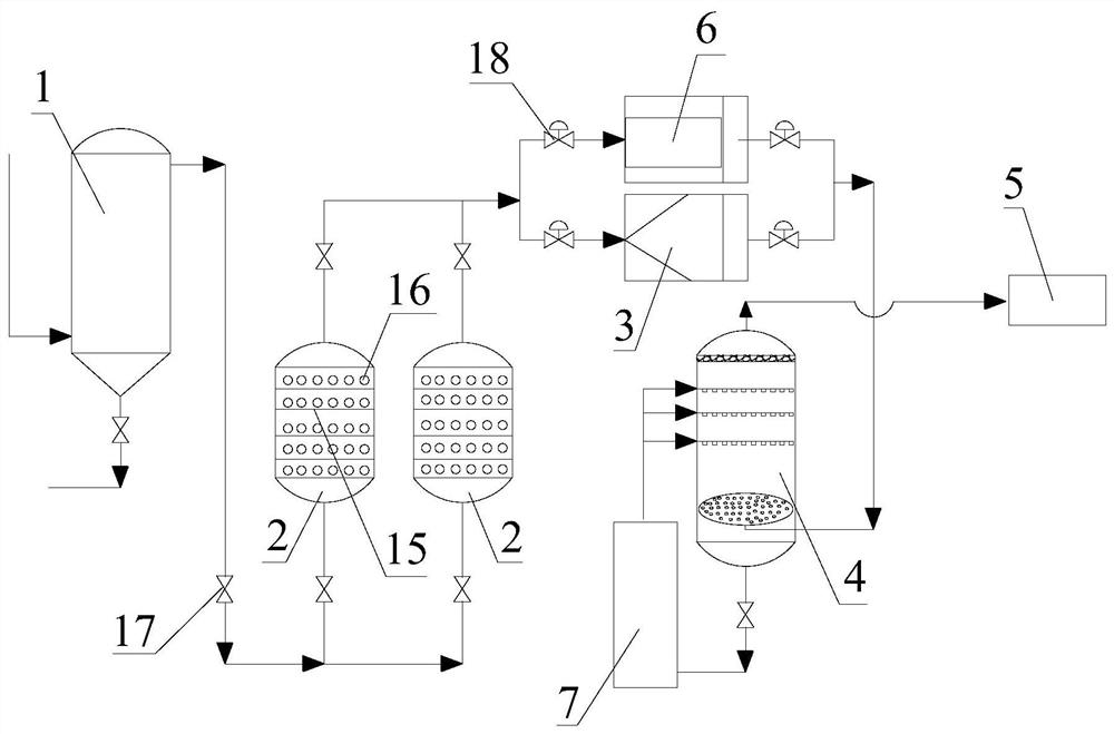
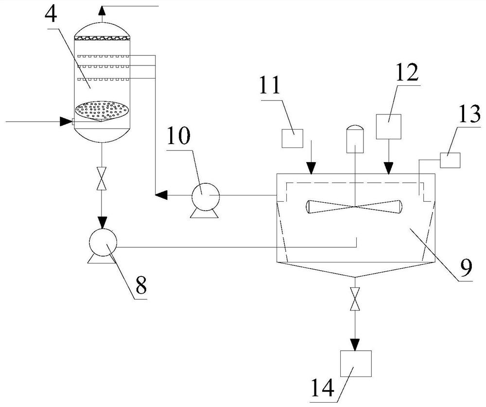
[0035] refer to figure 1 , figure 2 The shown blast furnace gas desulfurization process flow chart is carried out according to the following steps:

[0036] The temperature ~ 60 ℃ and pressure ~ 0.2MPa after fine dust removal by the bag filter 1 is sent to the parallel-connected hydrolysis catalytic tower 2 for hydrolysis catalytic desulfurization. The blast furnace gas is heated in the hydrolysis catalyst (γ-Al 2 O 3 As the carrier, the alkali metal K 2 Under the action of O is the active component catalyst), part of the COS is converted into H 2 S, the blast furnace gas is then depressurized by the blast furnace gas residual pressure turbine power generation device 3 or the pressure reducing valve 6 and then sent to the desulfurization cooling tower 4. In the desulfurization and cooling tower 4, the gas and the lye are in countercurrent contact, and an absorption reaction occurs, thereby completing the sulfide, HCl and CO in the gas. 2 The partial removal of acid gas c...

Embodiment 2

[0042] refer to figure 1 , figure 2 The shown blast furnace gas desulfurization process flow chart is carried out according to the following steps:

[0043] The temperature ~ 90 ℃ and pressure ~ 0.22MPa after being finely dedusted by the bag filter 1 are sent to the parallel-connected hydrolysis catalytic tower 2 for hydrolysis catalytic desulfurization. 2 As the carrier, the alkali metal K 2 Under the action of O is the active component catalyst), part of the COS is converted into H 2 S, the blast furnace gas is then depressurized by the blast furnace gas residual pressure turbine power generation device 3 or the pressure reducing valve 6 and then sent to the desulfurization cooling tower 4. In the desulfurization and cooling tower 4, the gas and the lye are in countercurrent contact, and an absorption reaction occurs, thereby completing the sulfide, HCl and CO in the gas. 2 The partial removal of acid gas can achieve the purpose of blast furnace gas purification. The g...

Embodiment 3

[0049] refer to figure 1 , figure 2 The shown blast furnace gas desulfurization process flow chart is carried out according to the following steps:

[0050] The temperature ~ 120 ℃ and pressure ~ 0.25MPa after the fine dust removal by the bag filter 1 is sent to the parallel connected hydrolysis catalytic tower 2 for hydrolysis catalytic desulfurization. The blast furnace gas is heated in the hydrolysis catalyst (ZrO 2 As the carrier, the alkali metal K 2 Under the action of O is the active component catalyst), part of the COS is converted into H 2 S, the blast furnace gas is then depressurized by the blast furnace gas residual pressure turbine power generation device 3 or the pressure reducing valve 6 and then sent to the desulfurization cooling tower 4. In the desulfurization and cooling tower 4, the gas and the lye are in countercurrent contact, and an absorption reaction occurs, thereby completing the sulfide, HCl and CO in the gas. 2 The partial removal of acid gas c...


PUM


Abstract

The invention relates to the technical field of desulfurization and purification treatment for blast furnace gas, and discloses a desulfurization method for blast furnace gas. The desulfurization method comprises the following steps: feeding the blast furnace gas having been subjected to fine dust removal by a bag-type dust remover into a hydrolysis catalytic tower for hydrolysis catalytic desulfurization so as to convert COS in the blast furnace gas into H2S in the hydrolysis catalytic tower under the action of a hydrolysis catalyst; and then allowing the blast furnace gas to pass through a blast furnace gas excess pressure turbine power generation device or a pressure reducing valve, subjecting the blast furnace gas to spraying, cooling and desulfurizing by a desulfurizing and cooling tower, then performing demisting by a demister, conducting purification and then feeding the purified gas into a gas pipe network. The invention also discloses a blast furnace gas desulfurization device. According to the desulfurization method and device for the blast furnace gas, the problem that SO2 of blast furnace gas users, such as a blast furnace hot blast stove, a heating furnace and a heat treatment furnace, exceeds a standard due to high total sulfur content of the blast furnace gas is effectively solved, and cost is low.

Description

technical field [0001] The invention relates to the technical field of blast furnace gas desulfurization purification treatment, in particular to a blast furnace gas desulfurization method and device. Background technique [0002] Blast furnace gas (BFG) is an important secondary energy source in iron and steel plants. After dust removal, blast furnace gas is often used alone as fuel for hot blast stoves, coke ovens and boilers, and can also be mixed with coke oven gas to become a calorific value of 1100-2000kcal / Nm 3 The mixed gas is used as fuel for soaking furnaces, heating furnaces, heat treatment furnaces, etc., and is used for ignition of sintering machines. With the improvement of environmental protection requirements in the iron and steel industry and the ultra-low emission limit requirements for sulfur dioxide in air pollutants such as blast furnace hot blast stoves and steel rolling heat treatment furnaces in the iron and steel industry's ultra-low emission opinion...

Claims


Application Information

Patent Timeline
IPC IPC(8): C10K1/00C10K1/02C10K1/34F28C3/06F27D17/00
CPCC10K1/004C10K1/024C10K1/34F27D17/00F28C3/06
Inventor 张垒王丽娜李富智付本全徐伟卢丽君刘璞刘尚超
Owner 武汉钢铁有限公司
Why Eureka
Try Eureka