Self-fusing unit and protection element using self-fusing unit

A technology for protection components and protection devices, applied in electrical components, emergency protection devices, structural parts, etc., can solve the problem that the high resistivity of lead-containing and its alloy solder is difficult to meet the demand, and achieves reduction of on-resistance and contact resistance, Satisfy the effect of large current flow and high conductivity

Pending Publication Date: 2021-01-22
SHANGHAI CHANGYUAN WAYON CIRCUIT PROTECTION CO LTD
View PDF0 Cites 0 Cited by
  • Summary
  • Abstract
  • Description
  • Claims
  • Application Information

AI Technical Summary

Problems solved by technology

However, with the miniaturization of electronic equipment, in order to increase the rated current in a limited

Method used


Image

  • Self-fusing unit and protection element using self-fusing unit
  • Self-fusing unit and protection element using self-fusing unit
  • Self-fusing unit and protection element using self-fusing unit

Examples


Embodiment 1

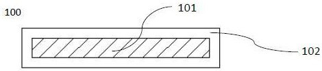
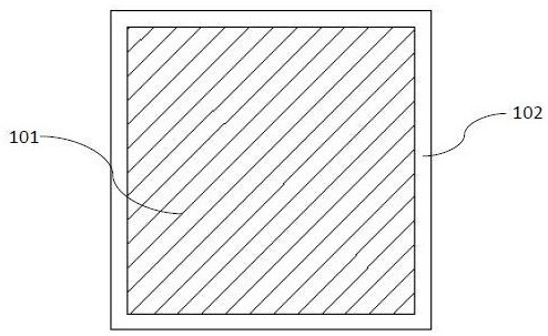
[0090] figure 1 is a schematic cross-sectional structure diagram of the self-fusing unit of the present invention; figure 2 is a schematic plan view of the self-fusing unit of the present invention.

[0091] A self-fusing unit 100 for protecting devices is a conductive sheath-core structure with a resistivity of 1.5-40 μΩ.cm, and the sheath-core structure includes an inner core 101 and an outer sheath 102, wherein the outer sheath 102 is in surface contact with the inner core 101 And fully coated on the periphery of the inner core 101, the surface of the inner core 101 is in contact with the outer sheath 102, the melting point and electrical conductivity of the outer sheath 102 are higher than the inner core 101, and the inner core 101 is a metal material or a polymer material, The outer sheath 102 is a silver-plated layer, which is used to inhibit the inner core material from swelling, deformation or melting out. In this embodiment, the outer sheath 102 adopts the preparati...

Embodiment 2

[0097] A self-fusing unit, such as figure 1 and figure 2 As shown, a core-sheath structure composed of an inner core 101 and an outer sheath 102, the inner core 101 is a metal material or a polymer material, and the outer sheath 102 is a silver-plated layer, and the outer sheath 102 of this embodiment adopts electroplating barrel plating silver The preparation method comprises the following steps in sequence:

[0098] In the first step, the material of the inner core 101 is made into a small-shaped substrate of 2.0*2.0*0.6mm by shearing or die stamping, and then placed in 80v% sulfuric acid aqueous solution at 40°C for 30 seconds. Deionized water cleaning, drying;

[0099] In the second step, put the SnCl of 15g / L of sensitizer 2 Sensitize in the solution for 200 minutes, take it out, wash it with deionized water, and dry it;

[0100] The third step, put the catalyst 0.1g / L of PdCl 2 Catalyze in the solution for 360 minutes, take it out, wash it with deionized water, dry...

Embodiment 3

[0103] A self-fusing unit, such as figure 1 and figure 2 As shown, a core-sheath structure composed of an inner core 101 and an outer sheath 102, the inner core 101 is a metal material or a polymer material, and the outer sheath 102 is a preparation method that combines calendering composite and electroplating barrel plating silver plating, in order Include the following steps:

[0104] In the first step, a 10 μm silver sheet is pasted on the upper and lower surfaces of the 0.6mm inner core 101, combined by calendering, shearing or die stamping, to make a small piece of 2.0*2.0, and then placed in a 40 Contact 80v% aqueous sulfuric acid solution at ℃ for 30 seconds, wash with deionized water, and dry;

[0105] In the second step, put sensitizer 15g / L SnCl 2 Sensitize in the solution for 200 minutes, take it out, wash it with deionized water, and dry it;

[0106] The third step, put the PdCl of catalyst 0.1g / L 2 Catalyze in the solution for 360 minutes, take it out, wash ...


PUM

PropertyMeasurementUnit
Thicknessaaaaaaaaaa
Thicknessaaaaaaaaaa
Surface roughnessaaaaaaaaaa

Abstract

The invention relates to a self-fusing unit for protecting a device, the self-fusing unit is of a conductive sheath core structure, and the resistivity is 1.5-40 [mu] omega.cm. The sheath core structure comprises an inner core and an outer sheath, the outer sheath material is in contact with the surface of the inner core material and completely wraps the inner core material, and the surface of theinner core material is in contact with the outer sheath material. The melting point and conductivity of the outer sheath material are higher than those of the periphery of the inner core material, and so that swelling and melt outflow of the inner core material are inhibited. According to the invention, not only can the requirement of large current flow in elements be met, but also the high-melting-point outer sheath material can lock the inner core material during reflow soldering mounting, so that the self-fusing unit is ensured to be in good condition through reflow soldering, and the phenomena of fusing, shrinkage, inner core material fusion and outflow and the like are avoided. The protection element provided by the self-fusing unit has the characteristic of high conductivity, and compared with the protection element with the same size, the rated current load of the protection element is greatly improved, and quick fusing can be realized due to the characteristic of lower meltingpoint.

Description

technical field [0001] The invention belongs to the technical field of circuit protection, and in particular relates to a self-fusing unit and a protection element applied thereto. Background technique [0002] Lithium-ion rechargeable batteries have been widely used in portable mobile devices such as mobile phones, notebooks, tablet computers, and digital cameras, and are increasingly being applied to energy storage batteries, two-wheel vehicle batteries, drones, sweepers, etc. in many new fields. While it has many superior performances, it still has disadvantages such as ignition, combustion, and explosion if the charging and discharging are not properly managed, especially when it is used in electric vehicles, because the number or volume of lithium-ion batteries used in it is very large. Combustion or explosion occurs, even life-threatening. [0003] In order to ensure the safety of users and electronic equipment, protection circuits are widely applied to lithium-ion b...

Claims


Application Information

Patent Timeline
IPC IPC(8): H01H85/06H01H85/08H01M50/581
CPCH01H85/06H01H85/08H01H69/02H01H85/165
Inventor 夏心俊韩乔磊钱朝勇李峰王开成程逸飞沈十林
Owner SHANGHAI CHANGYUAN WAYON CIRCUIT PROTECTION CO LTD
Why Eureka
Try Eureka