

C-EPS control strategy hardware-in-loop simulation development platform based on active fault tolerance
A C-EPS and control strategy technology, applied in design optimization/simulation, geometric CAD, special data processing applications, etc., can solve problems such as low precision, lack of precise loading and steering resistance, and poor simulation results
- Summary
- Abstract
- Description
- Claims
- Application Information
AI Technical Summary
Problems solved by technology
Method used
Image

Examples
Embodiment 1
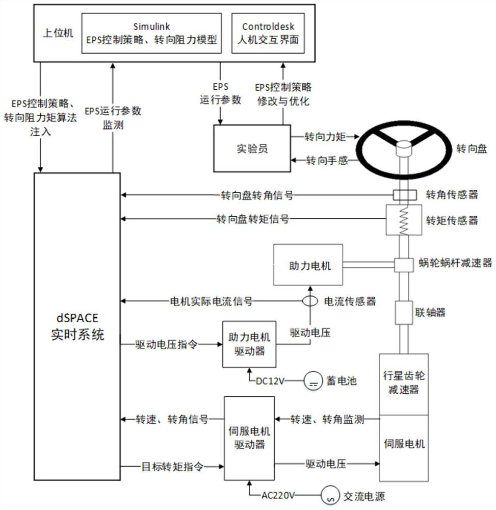
[0087] Embodiment 1: A hardware-in-the-loop simulation development platform based on active fault-tolerant C-EPS control strategy, such as figure 1 As shown, it includes hardware device, dSPACE real-time simulation system and host computer; dSPACE real-time simulation system is composed of DS1006 processor board and DS2202 HILI / O interface board. The required signals are generated, and the two are connected through the PHS++ bus; the DS1006 processor board is equipped with a 64-bit AMDOpteron as the main processor, which integrates a 256MB local memory for running the real-time model, and a 128MB global memory for communicating with the host computer For data exchange, it can be applied to rapid control prototyping (RCP) and hardware-in-the-loop (HIL), and can handle complex, large models that require extremely high processing performance, such as power systems and virtual vehicles. The DS2202 HIL I / O interface board provides 16 differential A / D acquisition channels, 24 PWM me...
Embodiment 2
[0142] Embodiment 2: The first half steps of this embodiment are the same as those in Embodiment 1, but the control mode switching module is switched to the failure mode in the C-EPS system control strategy.
[0143] In the fault mode, the faults of the rotation angle sensor, current sensor and torque sensor are described as follows:
[0144] the y if =y i +(Δ mi -1)y i +α;
[0145] Where: y if is the actual output value of the sensor; y i is the real value; α is the sensor stuck value; Δ m is the sensor fault gain, when Δ m is 1, when α is 0, the sensor has no fault;
[0146]
[0147] the y f =y+f s ;
[0148] In the formula: when i=1,2,3, represent angle sensor, current sensor and torque sensor respectively; y f is the sensor signal with fault; y is the system status output of the sensor with fault; f s is the error deviation value of the sensor;
[0149] Taking the mandrel of the steering column, the booster motor and the booster motor circuit as reference ...
PUM
 Abstract
Description
Claims
Application Information