Temperature difference power generation device with laminated structure and preparation method thereof

A technology of thermoelectric power generation and layered structure, which is applied in the manufacture/processing of thermoelectric devices, thermoelectric devices using only Peltier or Seebeck effect, etc. Resistance and other problems, to achieve low structural resistance and thermal resistance, improve thermoelectric conversion efficiency, and increase the effect of temperature difference

Pending Publication Date: 2021-01-29
HANGZHOU INNOVATION RES INST OF BEIJING UNIV OF AERONAUTICS & ASTRONAUTICS
View PDF0 Cites 2 Cited by
  • Summary
  • Abstract
  • Description
  • Claims
  • Application Information

AI Technical Summary

Problems solved by technology

There are mainly technical problems in the following aspects: (1) Due to the need for insulation between P-type and N-type thermoelectric material particles in the current thermoelectric power generation module, millimeter-level gaps are left between the particles, so that the proportion of thermoelectric materials per unit area Not high, not only the heat transfer efficiency is lost, but also the internal resistance of the power generation module is increased
However, since the thermoelectric material sheets of each stage of power generation sheet are installed on the ceramic substrate, the ceramic substrate will increase the weight and volume of the device
Moreover, each layer of ceramic plates will increase the longitudinal thermal resistance of the device, seriously reducing the thermoelectric conversion efficiency of the system

Method used


Image

  • Temperature difference power generation device with laminated structure and preparation method thereof
  • Temperature difference power generation device with laminated structure and preparation method thereof

Examples


Embodiment 1

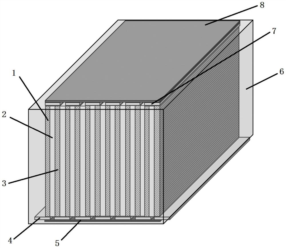
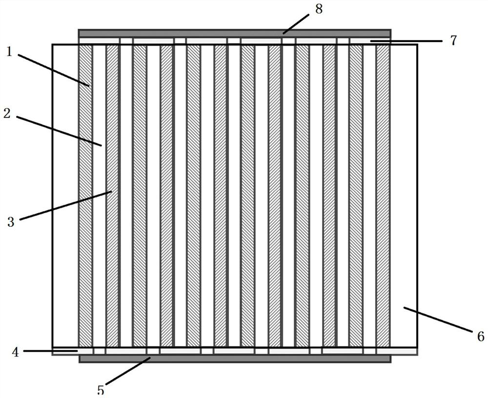
[0050] An embodiment of the present invention provides a method for preparing a thermoelectric power generation device with a laminated structure, including the following steps:

[0051] (1) Sb 2 Te 3 The ingot of the base semiconductor thermoelectric material is wire-cut into P-type thermoelectric sheets with a thickness of 400-1000 μm, and the crystal ingot of the BiTeSe-based semiconductor thermoelectric material is wire-cut into N-type thermoelectric sheets with a thickness of 400-1000 μm. The double-sided polishing of the P-type thermoelectric sheet and the N-type thermoelectric sheet has a surface roughness lower than 10 μm;

[0052] (2) Spin-coat polystyrene layers of insulating glue on both sides of the P-type thermoelectric sheet and the N-type thermoelectric sheet described in step (1), the thickness of the polystyrene layer is 5-50 μm;

[0053] (3) P-type thermoelectric sheets coated with polystyrene layers and N-type thermoelectric sheets are alternately attached...

Embodiment 2

[0059] This embodiment provides a method for preparing a thermoelectric power generation device with a laminated structure, including the following steps:

[0060] (1) P-type thermoelectric sheets and N-type thermoelectric sheets with a thickness of 10-200 μm were prepared respectively by screen printing;

[0061] Wherein, the preparation of the N-type thermoelectric sheet:

[0062] 1000 mesh Bi 2 Te 2.7 Se 0.3 After adding 95% alcohol, the powder is mixed with agate balls, sealed in an agate grinding tank, exhausted with nitrogen, and placed in a planetary ball mill at a speed of 300-500 rpm for 24 hours to obtain a superfine powder slurry. Take a quartz substrate with a thickness of 500 μm and place it on the lower end of the screen of the screen printing machine, smear the slurry on the screen and scrape the screen with a scraper to complete the printing. After the printed film is dried with a heat gun at 80°C, the above operations can be repeated to obtain an N-type th...

Embodiment 3

[0072] This embodiment provides a method for preparing a thermoelectric power generation device with a laminated structure, including the following steps:

[0073] (1) P-type thermoelectric flakes and N-type thermoelectric flakes with a thickness of 0.1-10 μm are prepared respectively by magnetron sputtering;

[0074] Wherein, the preparation of the N-type thermoelectric sheet:

[0075] The quartz substrate with a thickness of 50 μm was ultrasonically cleaned with deionized water, ethanol, and acetone, dried, and loaded into the magnetron sputtering sample stage. Bi 2 Te 2.7 Se 0.3 The target material is loaded into the target table of the magnetron sputtering equipment, and the vacuum is evacuated to reach the back pressure of 5×10 -4 Pa, inflate argon gas at a flow rate of 50-100 sccm, and maintain the pressure in the chamber at 0.5-3 Pa by adjusting the pumping valve. Heat the substrate to 200-400°C, start the DC sputtering power supply so that the sputtering power is ...


PUM


Abstract

The invention relates to a temperature difference power generation device with a laminated structure and a preparation method of the temperature difference power generation device, and the temperaturedifference power generation device structurally comprises a thermoelectric material layer, an insulating bonding layer, a top electrode, a bottom electrode, a top insulating layer, a bottom insulating layer and an insulating and heat-insulating packaging layer which are arranged in a laminated manner, the temperature difference power generation device has a long thermoelectric arm length, is beneficial to increasing the temperature difference, and can be used for a thermoelectric power generation environment with natural air heat dissipation. No gap exists between an N-type thermoelectric material and a P-type thermoelectric material, the proportion of the thermoelectric materials in unit area is large, the structural internal resistance and thermal resistance of the thermoelectric powergeneration module are effectively reduced, and the power generation efficiency is improved; the problems of moisture corrosion and the like can be eliminated by adopting simple edge packaging; the conductive connection between the N-type thermoelectric material and the P-type thermoelectric material adopts a simple spraying or sputtering process, and the insulating bonding layer connected with theelectrode is relatively thin, so that the thermal resistance of a heat transfer surface can be greatly reduced. The heat transfer surface of the temperature difference power generation device can beprocessed into any shape and is effectively attached to a curved surface heat source, and the maximum temperature difference power generation efficiency is obtained.

Description

technical field [0001] The invention belongs to the technical field of thermoelectric devices, and in particular relates to a thermoelectric power generation device with a laminated structure and a preparation method thereof. Background technique [0002] The thermoelectric power generation module is a device that uses semiconductor thermoelectric effect to convert thermal energy into electrical energy. It has the characteristics of no noise, long life, stable and reliable operation, and light weight. It can use various energy sources, including solid, liquid, and gaseous fuels, solar energy, and nuclear energy. , human body heating, waste heat and waste heat of various equipment to provide power for electrical equipment and devices, suitable for aerospace, military, exploration, portable equipment, passive sensors and other fields. [0003] The structure and manufacturing method of the current thermoelectric power generation module are usually to cut P-type and N-type therm...

Claims


Application Information

Patent Timeline
Patent Type & Authority Applications(China)
IPC IPC(8): H01L35/32H01L35/30H01L35/34
CPCH10N10/01H10N10/17H10N10/13
Inventor 潘锋邓元
Owner HANGZHOU INNOVATION RES INST OF BEIJING UNIV OF AERONAUTICS & ASTRONAUTICS
Why Eureka
Try Eureka