
Porous vacuum chuck and preparation method thereof

A vacuum suction cup and porous adsorption technology, which is applied in the direction of ceramic products, final product manufacturing, and other household appliances, etc. It can solve the problems of difficult precise control of the structure and orientation of holes, increased material cost and time cost, and limited number of holes. , to achieve the effect of reducing material cost and management cost, uniform adsorption force and small flow loss

Active Publication Date: 2021-02-26
ZHENGZHOU RES INST FOR ABRASIVES & GRINDING CO LTD
View PDF9 Cites 5 Cited by
  • Summary
  • Abstract
  • Description
  • Claims
  • Application Information

AI Technical Summary

Problems solved by technology

The pore diameter of the adsorption part made by the punching method is between 200μm-1.5mm, which is a through hole perpendicular to the adsorption surface, and the adsorption fixation is good. Such workpieces are sunken and deformed in the adsorption hole area, resulting in product defects, and the number of holes per unit area is limited, and the adsorption uniformity is poor, such as figure 1 as shown in (b)
The pore diameter of the adsorption parts made by stacking pores and adding pore-forming agents is between 30 μm and 2 mm. Due to the limitation of the pore-forming process, the porosity of the adsorption components is 20-50 vol%, and the structure and orientation of the pores are difficult to be precise. control, the orifice bends, resulting in flow loss such as figure 2 As shown in (b), the adsorption force is limited, so only flat workpieces that can completely cover the adsorption area can be adsorbed (that is, the adsorbed workpiece can only be the adsorbed workpiece 702 that completely covers the adsorption area). For workpieces of different sizes, it is necessary to purchase multiple types of porous vacuum suction cups to match. Once the shape and size of the workpiece change, the porous vacuum suction cups must be replaced and correspondingly debugged, which increases material costs and time costs.

Method used


Image

  • Porous vacuum chuck and preparation method thereof
  • Porous vacuum chuck and preparation method thereof
  • Porous vacuum chuck and preparation method thereof

Examples


Embodiment 1

[0044] After heating the camphene solvent in a constant temperature water bath to 80°C, add 20vol% of alumina powder with an average particle size of 1 μm, 2.5wt% of polyacrylamide and 2.5wt% of gum arabic to the solvent, and after stirring evenly, Place in a ball mill preheated to 80° C., and ball mill at a speed of 200 r / min for 8 hours to prepare a ceramic slurry.

[0045] Set the cooling platform to -50°C, place a bottom plate 10 (made of copper) with a thickness of 1 mm and a circular frame 11 made of polytetrafluoroethylene with a thickness of 20 mm in sequence, and quickly pour the prepared ceramic slurry into the mold , after cooling for 8 hours, the slurry was completely frozen, the frame 11 was removed, the frozen disc-shaped body was removed, and placed in a ventilated environment at 20°C for sublimation and drying for 24 hours.

[0046] The dried disc-shaped blank is put into an atmospheric pressure sintering furnace and sintered at 1550° C. to obtain porous alumin...

Embodiment 2

[0052] Heat the tert-butanol solvent in a constant temperature water bath to 50°C, add 60vol% of YSZ zirconia powder with an average particle size of 3μm, 2wt% of methylcellulose and 1wt% of polyvinyl alcohol into the solvent, and stir it evenly , placed in a ball mill preheated to 50°C, and ball milled at a speed of 800r / min for 4h to prepare a ceramic slurry.

[0053] Set the cooling platform to -80°C, place the aluminum mold bottom plate 10 with a thickness of 3mm and the polyurethane double-ring mold frame 11 with a thickness of 40mm in sequence, pour the prepared ceramic slurry into the ring mold quickly, and wait for cooling for 2 hours Finally, all the slurry is frozen, the frame 11 is removed, the frozen YSZ annular body is taken off, and placed in a ventilated environment at 10°C for sublimation and drying for 40 hours.

[0054] The dried YSZ annular body is put into an atmospheric sintering furnace and sintered at 1600°C to obtain porous zirconia ceramics. It also h...

Embodiment 3

[0061] Mix tert-butanol and water at a concentration of 70wt%, heat it in a constant temperature water bath to 60°C, and then add 40vol% of silicon carbide powder with an average particle size of 25μm, 4wt% of tetramethylammonium hydroxide and 6wt% of polyethylene Alcohol, after being uniformly stirred, placed in a ball mill preheated to 60°C, and ball milled at a speed of 600r / min for 20h to prepare a ceramic slurry.

[0062] Set the cooling platform to -40°C, place a stainless steel mold bottom plate 10 with a thickness of 5mm and a nylon square mold frame 11 with a thickness of 40mm in turn, pour the prepared ceramic slurry into the mold quickly, and wait for cooling for 8 hours Finally, the slurry is completely frozen, the frame 11 is removed, and the frozen square plate-shaped silicon carbide green body is removed, and placed in a ventilated environment at 5°C for sublimation drying for 48 hours.

[0063] The dried square plate-shaped silicon carbide green body is put int...


PUM

PropertyMeasurementUnit
thicknessaaaaaaaaaa
particle diameteraaaaaaaaaa
thicknessaaaaaaaaaa

Abstract

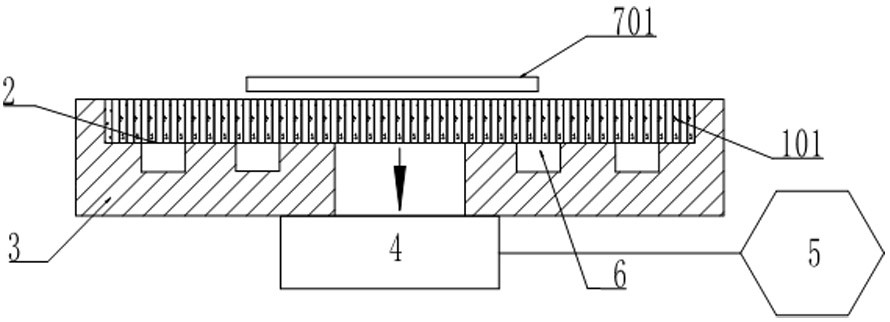
The invention belongs to the technical field of vacuum adsorption, and particularly relates to a porous vacuum chuck and a preparation method thereof. The porous vacuum chuck comprises a porous adsorption part, a sealing layer and a base, wherein the porous adsorption part is fixed on the base through the sealing layer, and a penetrating through hole is formed in the middle of the base; the porousadsorption part is made of one or more of aluminum oxides, zirconium oxides, zirconia toughened alumina (ZTA), silicon carbides, silicon nitrides, zinc oxides, titanium oxides, stannic oxides, hydroxyapatite or quartz; the sealing layer is made of ceramic, glass or resin, and the thickness of the sealing layer is 10-500 microns; and the base is made of aluminum oxides, zirconium oxides, ZTA, silicon carbides, silicon nitrides, quartz, stainless steel, titanium alloys or aluminum alloys. The porous vacuum chuck is small in flow loss, stable adsorption of an adsorbate can be achieved under thecondition that the adsorbate cannot completely cover an adsorption area, and product defects such as sunken deformation cannot be caused.

Description

technical field [0001] The invention belongs to the technical field of vacuum adsorption, and in particular relates to a porous vacuum suction cup and a preparation method thereof. Background technique [0002] Porous vacuum chuck, as a carrying platform that absorbs workpieces by vacuuming to form a negative pressure, has the characteristics of high porosity, high flatness, and uniform adsorption force, and is widely used in semiconductors, magnetic materials, and optoelectronic industries. In the semiconductor industry, porous vacuum chucks are the most widely used. They are mainly used in the front-end grinding, polishing, coating, testing, and back-cutting, scribing, cleaning, and handling processes. [0003] There are mainly two manufacturing methods for the adsorption parts of existing porous vacuum chucks, one is mechanical or laser drilling, such as figure 1 As shown in (a); one is to accumulate pores and add pore-forming agents to create pores, such as figure 2 (...

Claims


Application Information

Patent Timeline
Patent Type & Authority Applications(China)
IPC IPC(8): B65G47/91C04B35/10C04B38/06C04B35/48C04B35/565
CPCB65G47/91C04B35/10C04B38/067C04B35/48C04B35/565C04B2235/96B65G2201/02C04B38/0074C04B38/0054C04B38/0645Y02P70/50
Inventor 张昕宋运运孙正斌裴亚星刘勋
Owner ZHENGZHOU RES INST FOR ABRASIVES & GRINDING CO LTD
Learn More