Optical filter based on nanopore array structure

A nanohole array and optical filter technology, which is applied in the field of optical filters, can solve the problems of different, low stability, and difficult processing of optical filters.

Active Publication Date: 2021-04-09
XIDIAN UNIV
View PDF14 Cites 2 Cited by
  • Summary
  • Abstract
  • Description
  • Claims
  • Application Information

AI Technical Summary

Problems solved by technology

[0004] Two scholars, Bao and Bawendi, proposed a quantum dot filter in the article "A colloidal quantum dot spectrometer". This method puts quantum dots in colloids to construct a filter. Adjust the transmittance of the filter, the filter has a small size, and the filter has the same transmittance characteristics for polarized light in any direction, but the quantum dot colloid needs to be tightly sealed, otherwise, the colloid evaporates, It will cause the transmittance to change, thereby reducing the accuracy of spectral reconstruction, so the stability of the filter is not high, and the processing of the filter is more difficult
[0005] Xiaoxiu Zhu, a scholar from Beijing Institute of Technology, proposed a perovskite quantum dot filter in the article "Broadband perovskite quantum dotspectrometer beyond human visual resoluton". By changing the type of halide that constitutes the filter, its transmittance can be adjusted. The filter also has a smaller size and has the same transmittance characteristics for polarized light in any direction. At the same time, the filter is easier to manufacture than Bao's quantum dot colloid filter, but it still has stability. not high problem
[0006] Professor Yu from the University of Wisconsin-Madison proposed a nanophotonic structure filter composed of a photonic crystal plate in the article "Spectral analysis based on compressive sensing in nanophotonic structures". The filter has four layers from top to bottom. The structure is superimposed, and periodic pores are etched on the top Si layer. By changing the size of the pores and the arrangement of the pores, or changing the thickness and spacing of each layer of the filter, the filter can be achieved. The control of the transmittance of the filter, the size of the filter is small, the stability is high, but its structure is complex and difficult to process
[0007] In the article "On-chip near-infrared spectroscopy of CO2 using high resolution plasmonic filter array", Xinyuan Chong, a scholar at Oregon State University, proposed a filter based on plasmonic gratings. The filter is covered by a glass substrate The Au thin film on the Au thin film is etched with periodic slits to form a grating, and the surface of the grating is covered with SU-8 photoresist as a waveguide layer. By changing the periodicity of the grating, the transmittance of the filter can be adjusted. The filter has high stability, simple structure, and is easy to process, but the grating has directionality, and the filter has different transmittance characteristics for polarized light in different directions, which greatly affects the quality of spectral reconstruction

Method used


Image

  • Optical filter based on nanopore array structure
  • Optical filter based on nanopore array structure
  • Optical filter based on nanopore array structure

Examples


Embodiment 1

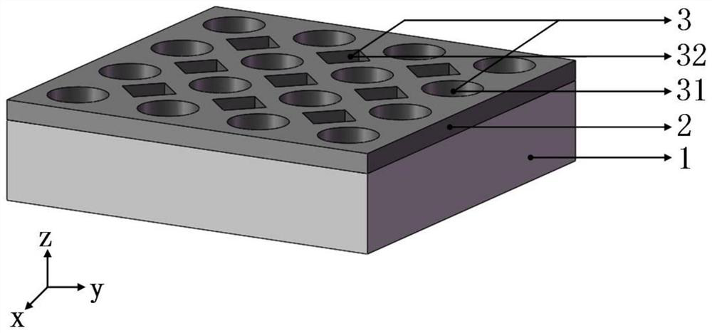
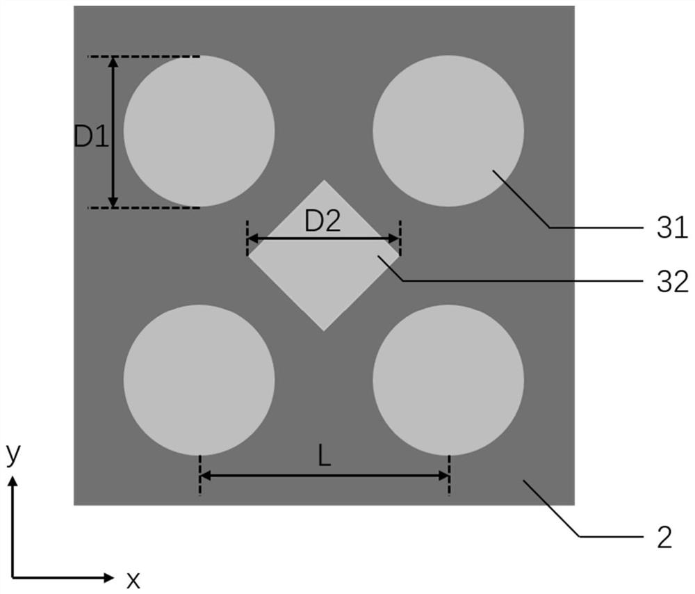
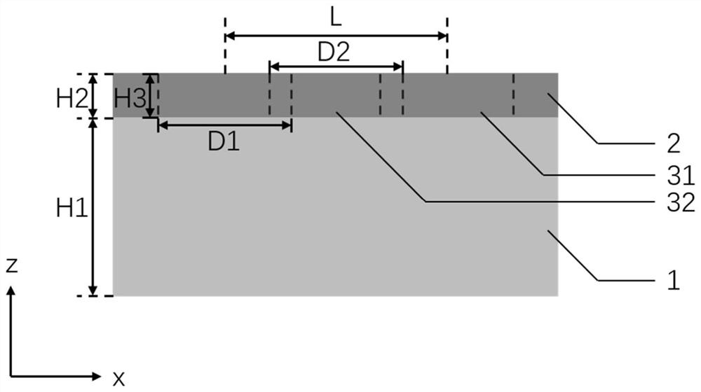
[0030] If the thickness H1 of the substrate 1 is 200nm, the thickness H2 of the metal film 2 is 50nm, and the period P is 300nm, according to the relationship of D1=D2=0.6*P, the diameter D1 of the circular hole 31 is 180nm, and the pair of rhombus holes 32 Diagonal line length D2 is 180nm, circular hole 31 is arranged according to square, and it has the same period P in row direction and column direction, and rhombus hole 32 is arranged according to square, and it has same period P in row direction and column direction, and positive The positions of the diamond-shaped holes 32 are arranged according to the circular holes 31 shifted along the row direction by a half-period P / 2 length and then along the column direction by a half-period P / 2 length, so as to obtain circular holes 31 staggered in rows or columns with a period P As with the regular rhombus hole 32 array, the distance from the center of any hole to the center of four adjacent holes around it is the same, forming a f...

Embodiment 2

[0032]Its structure is the same as that of Example 1, and the thickness of substrate 1 and metal film 2 is also the same as that of Example 1, the period P is changed to 360nm, and the circular hole is set according to the relationship of D1=D2=0.6*P=216nm The diameter D1 of 31 and the length D2 of the diagonal line of the rhombus hole 32 constitute a filter with a base thickness of 200nm, a metal film thickness of 50nm, and a nanohole array period of 360nm.

Embodiment 3

[0034] Its structure is the same as that of Example 1, and the thickness of substrate 1 and metal film 2 is also the same as that of Example 1, the period P is changed to 420nm, and the circular hole is set according to the relationship of D1=D2=0.6*P=252nm The diameter D1 of 31 and the length D2 of the diagonal line of the rhombus hole 32 constitute a filter with a base thickness of 200nm, a metal film thickness of 50nm, and a nanohole array period of 420nm.


PUM

PropertyMeasurementUnit
thicknessaaaaaaaaaa
thicknessaaaaaaaaaa
lengthaaaaaaaaaa

Abstract

The invention discloses an optical filter based on a nanopore array structure. The optical filter mainly solves the problems that an existing optical filter is complex in structure, large in machining difficulty and low in stability, and the same transmittance cannot be obtained for incident light in different polarization directions. The optical filter comprises a substrate (1), a metal film (2) and a nanopore array (3), wherein the metal film (2) is located on the substrate (1), the nanopore array (3) is etched on the surface of the metal film (2) by round holes (31) and regular rhombus holes (32) in a staggered arrangement mode according to a period P in rows or columns, and rows and columns where the round holes (31) are located are spaced from the rows and columns where the regular rhombus holes (32) are located by half a period, so that the distances from the center of any hole to the centers of the four adjacent holes around the hole are the same, and the transmittance of the optical filter is regulated and controlled by changing the period P. The optical filter is simple in structure, easy to manufacture and high in stability, can obtain the same transmissivity under the irradiation of incident light in different polarization directions, and can be used for spectrum reconstruction.

Description

technical field [0001] The invention belongs to the technical field of micro-nano optical devices, and in particular relates to an optical filter, which can be used for spectral reconstruction. Background technique [0002] The spectrum of a substance is called the "fingerprint" of the substance, and it is widely used in resource exploration, crop yield estimation, disease diagnosis and other fields. However, the current spectroscopic methods for obtaining spectra mainly include prism spectroscopic, grating spectroscopic and interferometer spectroscopic spectroscopic. Most of these spectroscopic methods require huge equipment and complex optical paths, which seriously restrict the application of spectrometry in field detection. At present, a new method of spectral reconstruction based on transmittance control is proposed. This method is to place a set of filters designed with a certain spectral transmittance in front of a set of detectors, and then through post-processing to...

Claims


Application Information

Patent Timeline
Patent Type & Authority Applications(China)
IPC IPC(8): G02B5/20
CPCG02B5/201
Inventor 刘德连叶云龙张建奇王昱程马向超解尧
Owner XIDIAN UNIV
Why Eureka
Try Eureka