
Modeling method for kinetic mass transfer model of CO2 electrochemical hydrogenation reactor

A hydrogenation reactor and kinetic model technology, applied in the field of electrochemical engineering, can solve the problems of not considering the dissolution and transfer process, difficult reactor model integration process design and parameter optimization, and high computing resource requirements

Pending Publication Date: 2021-04-20
DALIAN UNIV OF TECH
View PDF0 Cites 1 Cited by
  • Summary
  • Abstract
  • Description
  • Claims
  • Application Information

AI Technical Summary

Problems solved by technology

CO reported in the literature 2 The electrochemical hydrogenation reactor model includes the following three types: the document J Appl Electrochem (2007) 1117 is a zero-dimensional electrochemical hydrogenation model, and the CO 2 Kinetic parameters of hydrogenation, and the corresponding current densities of the products were then calculated from the potential, without taking into account CO 2 Dissolution and transfer process in the electrolyte; the literature Journal of The Electrochemical Society (2010) B1913 establishes the mass transfer process of electrolyte diffusion and electromigration in the electrolyte, and uses the Nernst-Plank equation to calculate the impact of ion mass transfer in the electrolyte on the reaction. but does not take into account CO 2 Dissolution and its influence on mass transfer in the reactor; the literature Journal of The Electrochemical Society (2015) F24 uses computational fluid dynamics (CFD) technology to obtain the gas in the reactor by solving the Navier-Stokes equation coupled with the electrode kinetics process Flow field distribution, but the CFD model requires high computing resources, and it is difficult to integrate the reactor model into the industrial process simulation software for process design and parameter optimization

Method used


Image

  • Modeling method for kinetic mass transfer model of CO2 electrochemical hydrogenation reactor
  • Modeling method for kinetic mass transfer model of CO2 electrochemical hydrogenation reactor
  • Modeling method for kinetic mass transfer model of CO2 electrochemical hydrogenation reactor

Examples


Embodiment Construction

[0050]The present invention will be further described below with reference to the accompanying drawings, and the following examples are used only to more clearly illustrate the technical solutions of the present invention without limiting the scope of the invention.

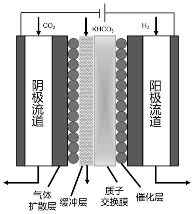
[0051]CO2infigure 1 Electrochemical hydrogenation in a fuel cell device having a buffer layer is carried out, and the cathode catalyst uses SN, the carrier is 2.0 mg cm.2, The anode catalyst uses PT / C with 0.5 mg of CM.2, Buffer uses 0.5m khco3Solution.

[0052]Hydrogen is reached by the proton of the anodic displacement electron dissociation, through the proton exchange membrane and buffer to the cathode, and CO2Hydrogenation reaction occurs, produces product formic acid and CO while accompanied by hydrogenation side effects.

[0053]Anode: h2→ 2h++ 2E-

[0054]Cathode: Co2+ 2E-+ H2O → HCOO-+ OH-

[0055]CO2+ 2E-+ H2O → Co + 2OH-

[0056]2h2O + 2E-→ h2+ 2OH-

[0057]According to the CO of the present invention2Hydrogenation reaction kin...


PUM


Abstract

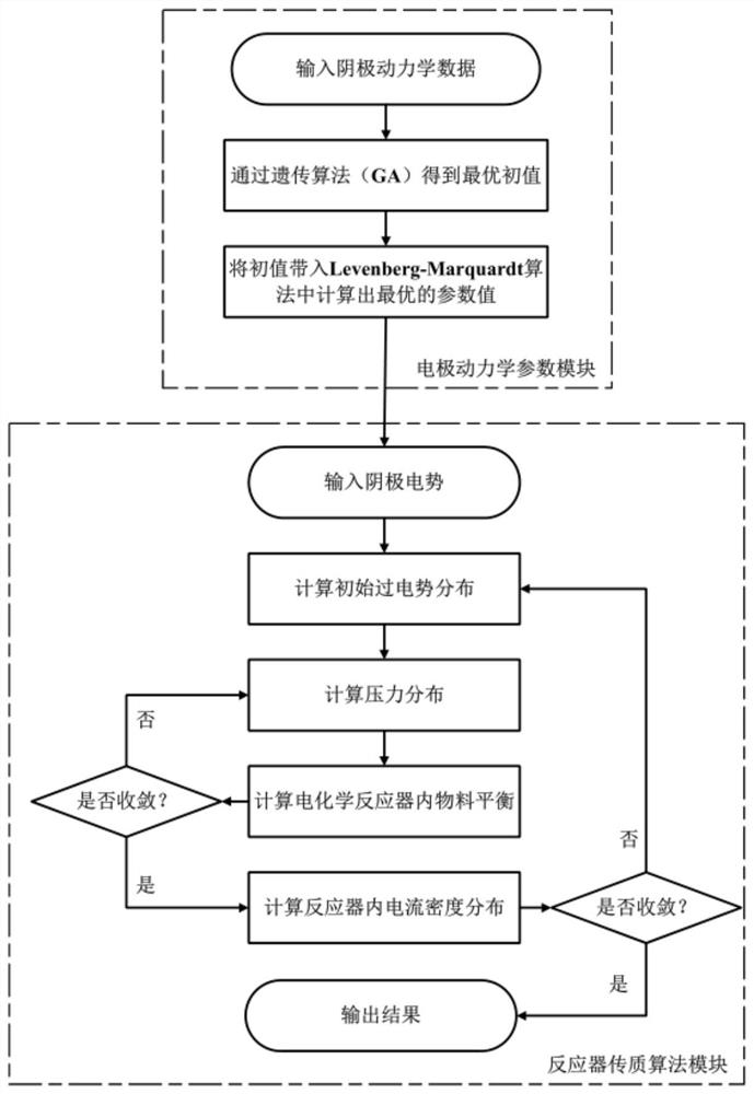
The invention relates to a modeling method for a kinetic mass transfer model of a CO2 electrochemical hydrogenation reactor, and belongs to the technical field of electrochemical engineering. The method comprises the following steps: S1, establishing an electrode kinetic model for generating formic acid, CO and a cathode hydrogen evolution side reaction through CO2 electro-catalysis; S2, optimizing and solving model parameters of electrode dynamics, wherein an optimized objective function is a minimum value of residual sum of squares of current densities of formic acid, carbon monoxide and hydrogen calculated by the model and an experimental result; S3, using a nonlinear optimization function in MATLAB for solving the model parameters; and S4, establishing a mass transfer coupling electrode kinetic model for the CO2 electrochemical hydrogenation reactor, discretizing a control equation of the gas mass transfer model by adopting a finite difference method, and realizing coupling calculation of cathode dynamics and a mass transfer equation by calculating overpotential distribution of each product of the cathode. The method is good in universality and has guiding significance for design of similar reactors.

Description

Technical field[0001]The present invention belongs to the field of electrochemical engineering, involving a CO2Modeling Method of Dynamic Mass Material Model of Electrochemical Hydrogenation Reactor.Background technique[0002]As the fossil energy is mining and used, the atmosphere is in the atmosphere2The content rises sharply. Co2Transforming to realize carbon cycles, is a method of solving the most promising in a greenhouse effect and an energy crisis. Co2The chemical properties are stable and need to provide additional activation energy. Common CO2The activation method mainly has three kinds of thermodynamics, optical chemistry and electrochemical. Thermodynamics is usually carried out in reactors such as fixed beds, requiring high temperature, high pressure reaction conditions, and excess hydrogen participation reactions will also reduce CO in reactors.2Split, resulting in low conversion rate and serious energy consumption; optical chemical use light energy provides CO2Activated ...

Claims


Application Information

Patent Timeline
Patent Type & Authority Applications(China)
IPC IPC(8): G16C10/00G06N3/12
Inventor 吴雪梅方远鑫贺高红崔福军肖武李祥村姜晓滨阮雪华代岩郭明钢
Owner DALIAN UNIV OF TECH
Learn More