
Crimping type IGBT sub-module and crimping type IGBT module

A crimping, sub-mold technology, applied in electrical components, electrical solid devices, circuits, etc., can solve the problems of high failure risk, complex structure, and high thermal resistance, reducing the number of stacked layers, simplifying the production process, and reducing the process. effect of difficulty

Pending Publication Date: 2021-04-20
ZHUZHOU CRRC TIMES SEMICON CO LTD
View PDF5 Cites 0 Cited by
  • Summary
  • Abstract
  • Description
  • Claims
  • Application Information

AI Technical Summary

Problems solved by technology

[0006] In view of the above problems, the present disclosure provides a crimping type IGBT sub-module and a crimping type IGBT module, which solves the technical problems of the existing crimping type IGBT modules that have a complex structure leading to high failure risk and high thermal resistance

Method used


Image

  • Crimping type IGBT sub-module and crimping type IGBT module
  • Crimping type IGBT sub-module and crimping type IGBT module
  • Crimping type IGBT sub-module and crimping type IGBT module

Examples


Embodiment 1

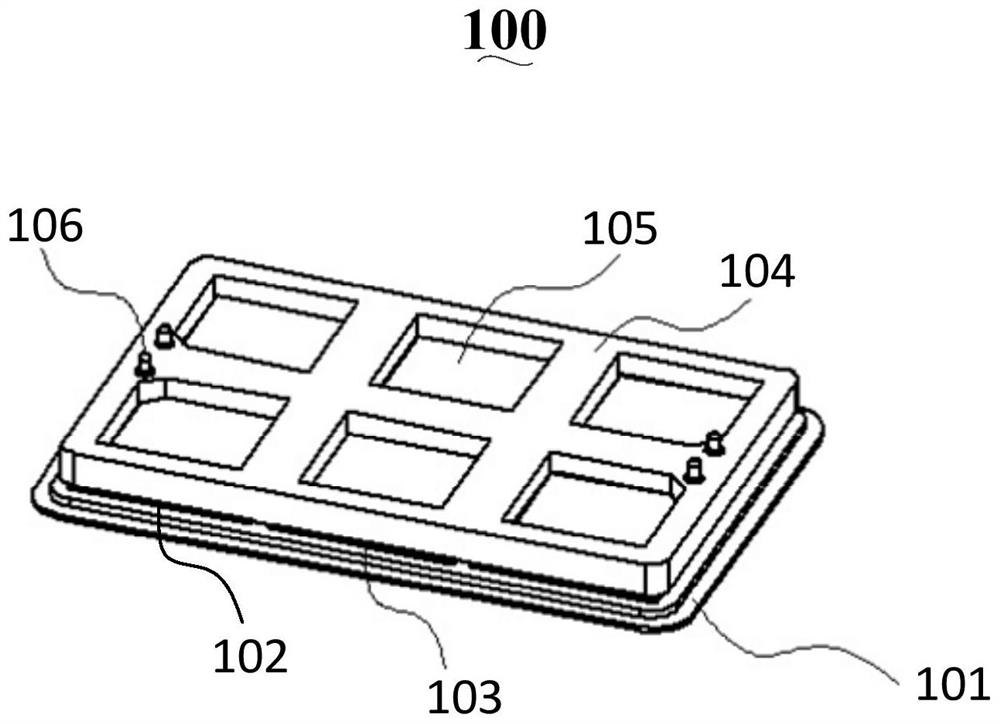
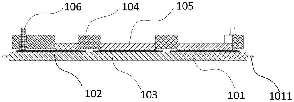
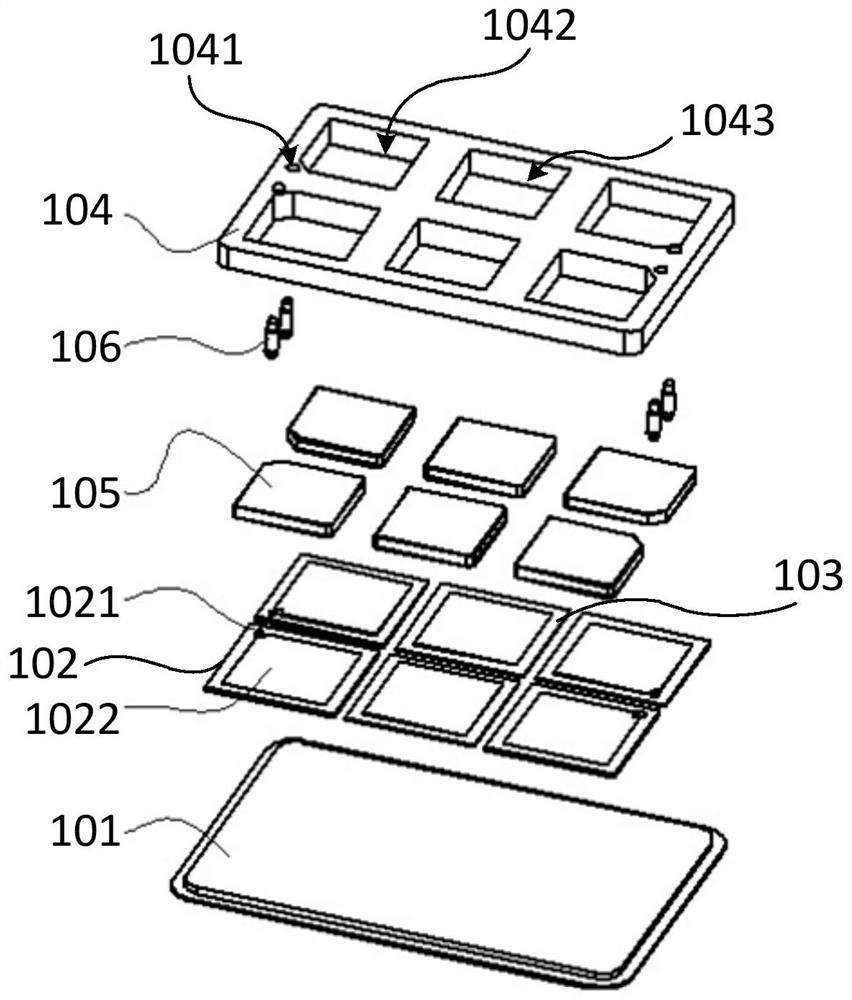
[0043] Such as figure 1 , figure 2 with image 3 As shown, this embodiment provides a crimp-type IGBT sub-module 100 , including a lower electrode plate 101 , an IGBT chip 102 , an FRD chip 103 , an insulating frame 104 , an upper electrode sheet 105 and a gate connector 106 .

[0044] The periphery of the lower electrode plate 101 (that is, the side wall of the lower electrode plate 101) is provided with a first skirt structure 1011, and the material of the lower electrode plate 101 can adopt high thermal conductivity, and the coefficient of thermal expansion (Coefficient of Thermal Expansion, CTE) and The matching materials of the IGBT chip 102 and the FRD chip 103 include (but not limited to) copper-molybdenum alloy or molybdenum.

[0045] A plurality of IGBT chips 102 and a plurality of FRD chips 103 are arranged above the lower electrode plate 101 at intervals. The number of IGBT chips 102 is greater than or equal to 2, and the number of FRD chips 103 is set according...

Embodiment 2

[0057] Such as Figure 4 with Figure 5 As shown, this embodiment provides a crimping type IGBT module on the basis of the first embodiment, including the crimping IGBT sub-module 100, the PCB circuit board 200 and the casing (not marked in the figure) in the first embodiment ).

[0058] The PCB circuit board 200 is located above the crimping type IGBT sub-module 100 . Wherein, the PCB circuit board 200 is in contact with the gate connector 106 of the press-fit IGBT sub-module 100, so as to gather the gates of all the press-fit IGBT sub-modules 100 to the total grid on the PCB circuit board 200 . The PCB circuit board 200 includes a plurality of fourth openings 201 for exposing the upper electrode pads 105 of each crimp-type IGBT sub-module 100 . That is to say, the PCB circuit board 200 is mainly used to lead out the gate of the crimp-type IGBT sub-module 100 .

[0059] The tube case includes a tube cover 300 and a tube base 400 , the tube cover 300 is located above the ...


PUM


Abstract

The invention provides a crimping type IGBT sub-module and a crimping type IGBT module. The crimping type IGBT sub-module comprises a plurality of IGBT chips and a plurality of FRD chips, wherein the IGBT chips and the FRD chips are arranged above a lower electrode plate at intervals. The crimping type IGBT module comprises: a plurality of crimping type IGBT sub-modules. and a tube shell comprising a tube cover and a tube base, wherein the tube base is of a hollow structure, and the tube base comprises a plurality of fifth open holes and third skirt edge structures located around the fifth open holes; the fifth open holes are used for exposing the lower electrode plate of each crimping type IGBT sub-module; and the third skirt edge structure is in contact with the first skirt edge structure of the lower electrode plate so as to realize sealed packaging. According to the crimping type IGBT module, the tube base with the hollow structure is adopted, so that the thermal resistance on a heat flow path is reduced, under the structure, the module sealing can be realized by adopting a cold pressure welding or argon arc welding mode, and the production process is simplified.

Description

technical field [0001] The present disclosure relates to the technical field of semiconductor devices, in particular to a crimping type IGBT sub-module and a crimping type IGBT module. Background technique [0002] As a typical representative of power electronic devices, insulated gate bipolar transistor (Insulated Gate Bipolar Transistor, IGBT) is widely used in modern power electronics. It not only has the advantages of high input impedance, low control power, simple drive circuit, high switching speed and low switching loss of Metal-Oxide-Semiconductor Field-Effect Transistor (MOSFET), but also has bipolar Bipolar Junction Transistor (BJT) has the advantages of high current density, low saturation voltage, and strong current handling capability, so it is an ideal switching device in the field of power electronics. [0003] With the continuous improvement of power transmission capacity, higher and higher requirements are put forward for the power capacity, performance and...

Claims


Application Information

Patent Timeline
IPC IPC(8): H01L25/18H01L23/13H01L23/10
Inventor 张文浩石廷昌常桂钦李寒李亮星董国忠
Owner ZHUZHOU CRRC TIMES SEMICON CO LTD
Learn More