Lithium niobate film electro-optical modulator chip and modulator

An electro-optic modulator, lithium niobate technology, applied in the direction of instruments, optics, nonlinear optics, etc., can solve the problems of low electro-optic modulation efficiency, long total device length, increase the total device length, etc., achieve high electro-optic modulation efficiency, small Effect of waveguide mode distribution and overall length reduction

Active Publication Date: 2021-05-25
天津领芯科技发展有限公司
View PDF13 Cites 2 Cited by
  • Summary
  • Abstract
  • Description
  • Claims
  • Application Information

AI Technical Summary

Problems solved by technology

[0006]Secondly, the low electro-optic modulation efficiency of existing lithium niobate electro-optic modulators requires a sufficiently long modulation electrode length to achieve a lower half-wave voltage , so the total length of the device also needs to be longer;
[0007]Third, existing high-order modulators such as lithium niobate QPSK electro-optic modulators also need to add bias electrodes to achieve the stability of the operating point of each MZ modulator As well as the phase delay between the two MZ modulators, the introduction of each set of bias electrodes also increases the overall length of the device;
[0008]Fourth, the existing lithium niobate electro-optic modulator generally has the input and output ports of the radio frequency electrical signal at the bottom of the device, and the optical signal (ie optical fiber) The input and output ports are on the left and right sides of the device, and the fiber coupling structure and the protection structure of the fiber port inevitably increase the overall length of the device

Method used


Image

  • Lithium niobate film electro-optical modulator chip and modulator
  • Lithium niobate film electro-optical modulator chip and modulator
  • Lithium niobate film electro-optical modulator chip and modulator

Examples


Embodiment 1

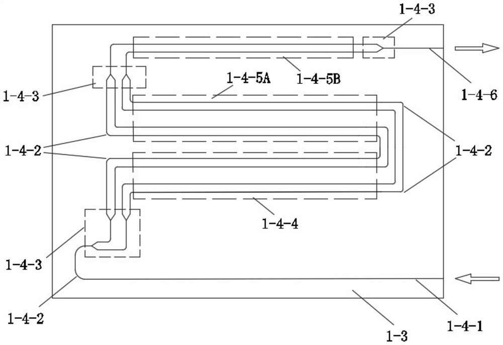
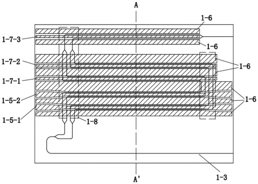
[0045] Such as image 3 , Figure 4 As shown, the lithium niobate thin film electro-optic modulator chip includes: base wafer 1-1, adhesive layer film 1-2, lithium niobate thin film substrate 1-3, input end optical waveguide 1-4-1, 90° curved waveguide 1-4-2, Y branch waveguide 1-4-3, optical waveguide in radio frequency modulation area 1-4-4, optical waveguide in the first bias control area 1-4-5A, optical waveguide in the second bias control area 1-4-5B, output optical waveguide 1-4-6, radio frequency modulation electrode 1-5-1, radio frequency modulation electrode 2 1-5-2, ground electrode 1-6, bias control electrode 1-7 -1. Bias control electrode two 1-7-2, bias control electrode three 1-7-3, buffer layer film 1-8.

[0046] The base wafer 1-1 provides mechanical support for the lithium niobate thin film substrate 2, and its constituent materials can be any one of lithium niobate, lithium tantalate, silicon, quartz, sapphire, etc., preferably silicon is used as the materi...

Embodiment 2

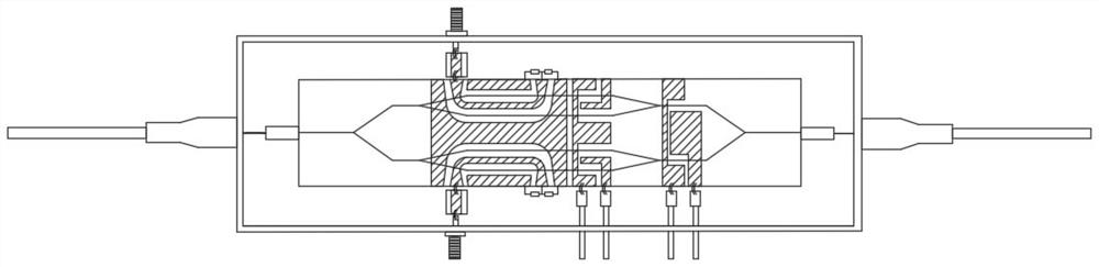
[0072] This embodiment is an improvement carried out on the basis of Embodiment 1, as Figure 5 As shown, a lithium niobate thin film electro-optic modulator in this embodiment includes: a lithium niobate thin film electro-optic modulator chip, an optical fiber crystal carrier block 2, an optical fiber 3, a microstrip circuit ceramic plate 4, a matching resistor 5, and lead pins 6. Radio frequency connector 7, bonding gold wire 8, packaging tube shell 9.

[0073] The lithium niobate thin film electro-optic modulator chip has the structure of the lithium niobate thin film electro-optic modulator chip in Embodiment 1.

[0074] The optical fiber crystal carrier block 2 can be selected from one of materials such as lithium niobate, lithium tantalate, glass, quartz, silicon, etc., and there are grooves in the shape of round holes, square grooves, semicircular grooves, and V-shaped grooves on it. for placing fibers. The optical fiber 3 is a single-mode non-polarization-maintaining...


PUM

PropertyMeasurementUnit
Widthaaaaaaaaaa
Thicknessaaaaaaaaaa
Thicknessaaaaaaaaaa

Abstract

The invention discloses a lithium niobate film electro-optical modulator chip. A Y-branch waveguide, a waveguide optical path of a radio frequency modulation part and a waveguide optical path of a bias voltage control part are separated in space, and a 90-degree bent waveguide is used for connecting the waveguide optical paths, so that the length of the lithium niobate film electro-optical modulator chip can be remarkably shortened; in addition, the invention also provides a lithium niobate film electro-optical modulator, optical fibers serving as an optical input port and an optical output port are placed on the same side of a lithium niobate film electro-optical modulator chip, and the optical fiber port protection structure of the electro-optical modulator is placed on the same side of the device. The total length of the lithium niobate film electro-optical modulator can be effectively shortened.

Description

technical field [0001] The invention can be applied to the technical fields of optical fiber communication and microwave optical fiber link, and in particular relates to a lithium niobate thin film electro-optical modulator chip and a modulator. Background technique [0002] Quadrature phase-shift keying (QPSK) technology has become an optical transmission technology in recent years, especially in dense wavelength division multiplexing (DWDM) systems, due to its advantages of high spectral utilization, high signal-to-noise ratio and high dispersion tolerance. A widely used modulation format for bit rate transmission. [0003] Electro-optic modulators based on the linear electro-optic effect of lithium niobate crystals have played a very important role in the development of optical fiber communication networks due to their low loss, low chirp, high bandwidth, and high extinction ratio. Although optical transmitters using directly modulated lasers or electro-absorption modula...

Claims


Application Information

Patent Timeline
IPC IPC(8): G02F1/035
CPCG02F1/035
Inventor 李萍
Owner 天津领芯科技发展有限公司
Why Eureka
Try Eureka