Liquefied air energy storage and thermoelectric power generation coupling system and working method thereof

A technology for thermoelectric power generation and air liquefaction, which is applied in liquefaction, refrigeration and liquefaction, generator/motor and other directions, and can solve the problems of low energy storage system efficiency, increased system complexity, and environmental thermal pollution.

Active Publication Date: 2021-05-28
XI AN JIAOTONG UNIV
View PDF19 Cites 6 Cited by
  • Summary
  • Abstract
  • Description
  • Claims
  • Application Information

AI Technical Summary

Problems solved by technology

During the working process of the liquefied air energy storage system, 100% air liquefaction cannot be achieved due to the limited available cold energy, so that the compression heat generated in the energy storage stage cannot be completely consumed in the energy release stage, resulting in a large amount of heat loss, which not only affects the overall system Cycle operation efficiency is adversely affected, and environmental heat pollution is also generated
[0003] In order to solve the problem of low efficiency of the energy storage system caused by excess compression heat, an external cycle can usually be introduced to use the excess compression heat to drive the power plant to generate additional energy output, such as: organic Rankine cycle and kalina cycle, etc., but the external power cycle The introduction of the system will not only cause a significant increase in the complexity of the system, but also greatly increase the equipment investment and operation and maintenance costs of the system

Method used


Image

  • Liquefied air energy storage and thermoelectric power generation coupling system and working method thereof
  • Liquefied air energy storage and thermoelectric power generation coupling system and working method thereof
  • Liquefied air energy storage and thermoelectric power generation coupling system and working method thereof

Examples


Embodiment 1

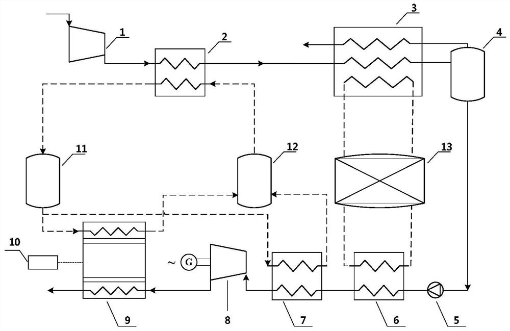
[0038] see figure 1 , the liquefied air energy storage-thermoelectric power generation coupling system of the present invention includes an air compressor 1, a post-stage air cooler 2, a cold box 3, a liquid air storage tank 4, a cryogenic liquid pump 5, an air vaporizer 6, and a pre-stage Air reheater 7, air expander 8, thermoelectric power generation device 9 and other main components also include high temperature heat storage tank 11, normal temperature heat storage tank 12 and a low temperature cold storage tank 13. The applicable working conditions of this embodiment are: the exhaust temperature of the air expander 8 is relatively low and must not be higher than the ambient temperature, so as to ensure the efficient operation of the thermoelectric power generation device.

[0039]The air inlet of the air compressor 1 is connected to the ambient atmosphere, and the exhaust port of the air compressor 1 is connected to the hot end of the after-stage air cooler 2 and the hot ...

Embodiment 2

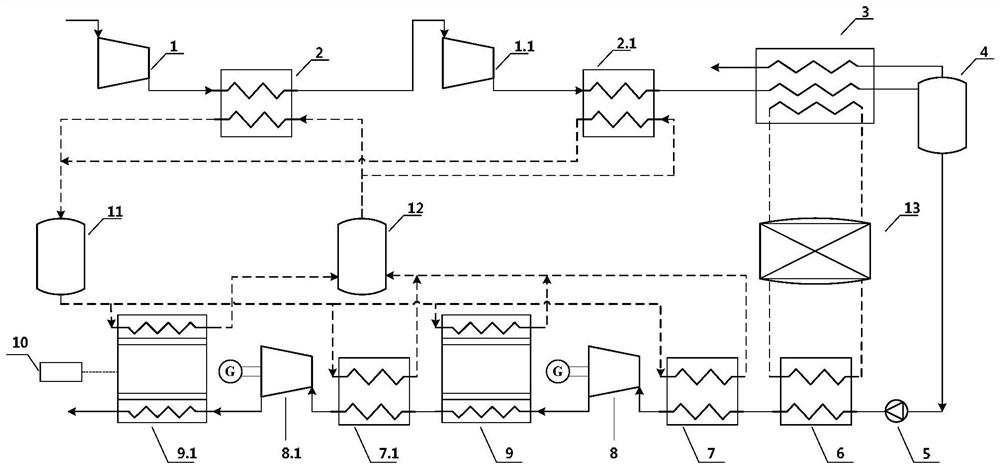
[0054] figure 2 It is a schematic diagram of a coupling system adopting a two-stage compression and two-stage expansion scheme in the present invention. Compared with Embodiment 1, the improvement is that the air compression device consists of a first-stage air compressor 1, a first-stage after-stage air cooler 2, The second-stage air compressor 1.1 and the second-stage after-stage air cooler 2.1 are composed and connected in sequence. The outlet of the hot end of the second-stage after-stage air cooler 2.1 is connected with the inlet of the hot end of the cold box 3; the air expansion device and the temperature difference The power generation device consists of a first-stage front air reheater 7, a first-stage air expander 8, a first-stage thermoelectric power generation device 9, a second-stage front air reheater 7.1, a second-stage air expander 8.1 and a first-stage The second-stage thermoelectric power generation device 9.1 is composed and connected in sequence, and the o...

Embodiment 3

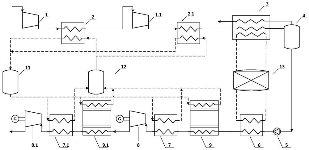
[0056] image 3 It is a schematic diagram of the pre-stage thermoelectric power generation device of the present invention, and its improvement compared with Example 2 is that the thermoelectric power generation device is no longer installed at the outlet of the last-stage air expander, but the inlet of the air reheater before the first stage Install a thermoelectric power generation device; the outlet of the air vaporizer 6 is sequentially connected with the first-stage thermoelectric power generation device 9 cold-end heat exchanger, the first-stage pre-stage air reheater 7 cold end, the first-stage air expander 8, and the second-stage 9.1 cold end heat exchanger of the thermoelectric power generation device, 7.1 cold end of the second-stage pre-stage air reheater are connected with the second-stage air expander 8.1, and the outlet of the second-stage air expander 8.1 is communicated with the atmosphere. The working method of the system is the same as that of Embodiment 1, a...


PUM


Abstract

The invention discloses a liquefied air energy storage and thermoelectric power generation coupling system and a working method thereof. The system comprises an air compression device, an air liquefaction device, a liquid air pressurizing gasification device, an air expansion device, a thermoelectric power generation device and a heat and cold storage device. According to the working method of the system, in the energy storage stage, the air compression device, the air liquefaction device and the heat and cold storage device are in a working state to consume external electric energy to realize air liquefaction storage and compression heat recovery; and in the energy release stage, a supercritical working mode is adopted, the liquid air pressurizing gasification device, the air expansion device, the thermoelectric power generation device and the heat and cold storage device are in the working state, power is supplied outwards through the air expansion device and the thermoelectric power generation device, and liquid air gasification latent heat recovery is completed. The semiconductor thermoelectric power generation device is introduced into the liquefied air energy storage system, compression waste heat and expansion waste cold are used for driving the thermoelectric power generation device to output extra electric energy, the operation efficiency of the system can be improved, and waste heat emission can be reduced.

Description

technical field [0001] The invention belongs to the technical field of energy storage and waste heat recovery, and relates to a compressed air energy storage system, in particular to a liquefied air energy storage-thermoelectric power generation coupling system and a working method thereof. Background technique [0002] Air Liquide energy storage technology is one of the most promising large-scale energy storage technologies. It not only has significant peak-shaving and frequency-regulating capabilities, but also can realize unsteady storage and stable output of renewable energy such as wind power and photovoltaic power generation. During the working process of the liquefied air energy storage system, 100% air liquefaction cannot be achieved due to the limited available cold energy, so that the compression heat generated in the energy storage stage cannot be completely consumed in the energy release stage, resulting in a large amount of heat loss, which not only affects the o...

Claims


Application Information

Patent Timeline
Patent Type & Authority Applications(China)
IPC IPC(8): F01K3/14F01B23/10F01B21/00F04B41/02F04B39/06H02N11/00F28D20/00F25J1/00
CPCF01K3/14F01B23/10F01B21/00F04B41/02F04B39/06H02N11/002F28D20/0034F25J1/0012Y02E60/14F25J1/0045F25J2205/24F25J1/0251F25J1/0242F25J2230/30F25J2230/06F25J2240/90F25J2230/04F25J1/004F25J1/0201Y02E60/16
Inventor 刘青山刘迎文何志龙
Owner XI AN JIAOTONG UNIV
Why Eureka
Try Eureka