
3D printing device and method for oriented crystal or single crystal high-temperature alloy and product

A technology of 3D printing and high-temperature alloys, which is applied in the field of additive manufacturing, and can solve problems such as the manufacture of complex hollow turbine blades

Inactive Publication Date: 2021-06-04
HUAZHONG UNIV OF SCI & TECH
View PDF16 Cites 6 Cited by
  • Summary
  • Abstract
  • Description
  • Claims
  • Application Information

AI Technical Summary

Problems solved by technology

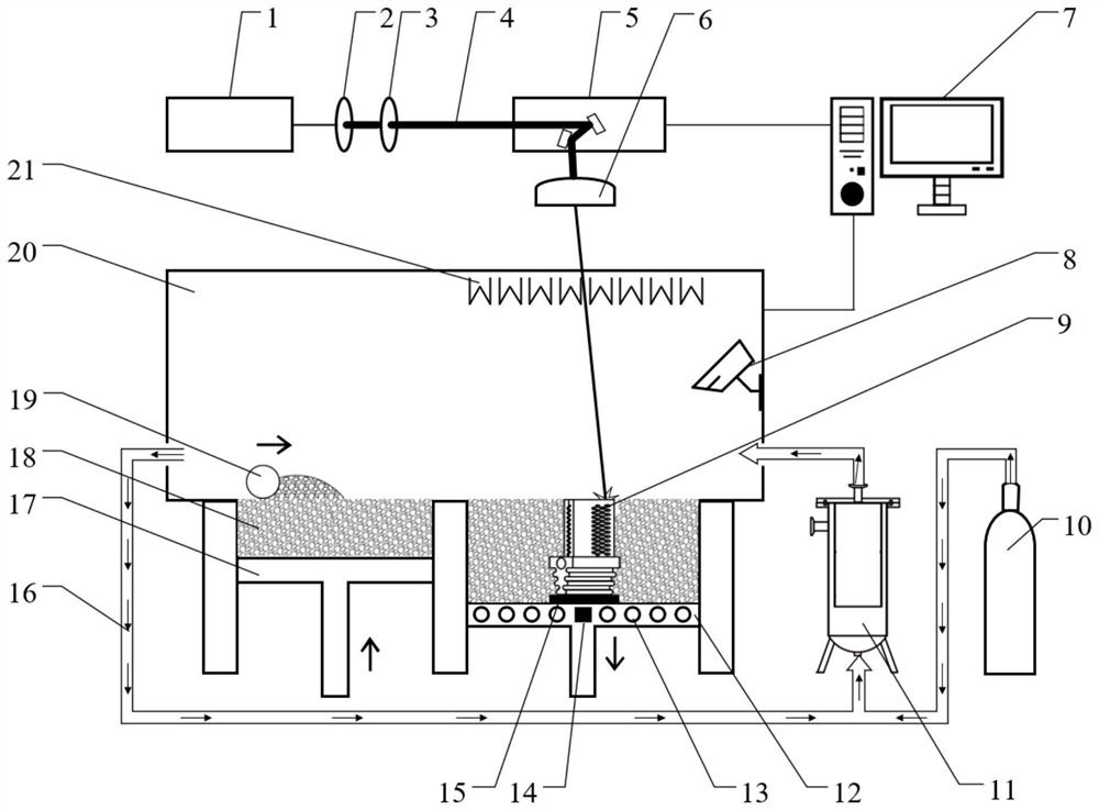
[0011] In view of the above defects or improvement needs of the prior art, the present invention provides a 3D printing device, method and product of directional crystal or single crystal superalloy, by using laser 3D printing technology to replace the traditional directional solidification casting technology, and changing the focus spot The energy distribution and the temperature distribution of the external environment are aimed at improving the stability of the molten pool, reducing the influence of the heat-affected zone during multi-layer stacking, reducing the energy difference inside the molten pool and the intensity of Marangoni convection, and controlling the internal temperature gradient of the molten pool. Strictly from top to bottom, reduce or even eliminate miscellaneous crystals such as equiaxed crystals, and achieve stable epitaxial growth of oriented crystals or single crystals along [001] layer by layer, thereby solving the technical problem of difficult manufacturing of complex hollow turbine blades in the prior art

Method used


Image

  • 3D printing device and method for oriented crystal or single crystal high-temperature alloy and product
  • 3D printing device and method for oriented crystal or single crystal high-temperature alloy and product
  • 3D printing device and method for oriented crystal or single crystal high-temperature alloy and product

Examples


Embodiment 1

[0075] In order to test the reliability of the above-mentioned device for forming oriented crystals or single crystals, taking a rectangular laser spot as an example, the finite volume simulation method is used to simulate the characteristics of the molten pool during the laser forming process, and the shape of the molten pool, the internal temperature field and the flow field are predicted. distribution, it can be seen that:

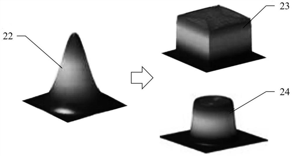
[0076] For melt pool shapes, see image 3 with Figure 4 In the picture on the left, because the internal energy of the Gaussian laser is high in the middle and low on both sides, the molten pool formed is deep and narrow, in the shape of an awl, while the internal energy distribution of the rectangular laser on the right is uniform, so the formed molten pool is shallow and wide. It is flat. Theoretically, the direction of the temperature field inside the flat molten pool is more uniform, the flow field is more stable, the bottom of the molten pool is...

Embodiment 2

[0081] In order to test the reliability of the above-mentioned device for forming oriented crystals or single crystals, a single-pass test is carried out to check whether the crystals in the molten pool on the side of the single pass grow epitaxially along the single-crystal substrate. Specific steps are as follows:

[0082] (1) Use UG three-dimensional modeling software to draw a 10×10×10mm block, and export the STL file format for future use. In a single-pass experiment, set the scanning distance to more than 10mm to form a single cladding pass;

[0083] (2) Put the DD91 nickel-based single crystal superalloy powder into a vacuum oven, and dry it at 80°C for 8 hours to remove the moisture on the surface of the powder. alloy rod cut into The wafer is used as a forming substrate, and its internal crystals are required to grow along [001], and the orientation angle deviation is less than 5°. One of the circular sections is selected as the deposition surface, and it is polishe...

Embodiment 3

[0089] In order to test the reliability of forming oriented crystals or single crystals by the above-mentioned device, a multi-pass lap test is carried out to check whether the crystals at the multi-pass laps grow epitaxially along the single crystal substrate. The specific steps are substantially the same as in Example 2, and the laser forming process parameters are power 300W, scanning speed 500mm / s, layer thickness 50μm, and scanning distance 100μm.

[0090] Depend on Figure 7 In (a) and (b), it can be seen that when multiple layers are overlapped, the crystal in the molten pool can continue to grow in the [001] orientation of the single crystal substrate. That is to say, by correcting the laser spot shape and energy distribution, and cooperating with the forced temperature difference unit, it is possible to realize the strict [001] orientation growth of crystals in the molten pool during multi-channel overlapping, without generating miscellaneous crystals, freckles, small...


PUM


Abstract

The invention belongs to the related technical field of additive manufacturing, and discloses a 3D printing device and method for an oriented crystal or single crystal high-temperature alloy and a product. The device comprises a forming unit, a shape righting light path unit and a forced temperature difference unit; a DOE diffraction optical element is arranged in the shape righting light path unit, and the shape righting light path unit is used for converting laser spot energy generated by a laser emitting element into uniform distribution from Gaussian distribution; the forced temperature difference unit is arranged in the forming cavity and comprises an infrared heating pipe and a cooling pipeline, heating is conducted above a cooling substrate through the infrared heating pipe, cooling is conducted in the cooling substrate through the cooling pipeline, thus an environment temperature field with the temperature strictly and gradually reduced is formed above the cooling substrate, and then crystals grow in the opposite direction of gradually-reduced temperature when a molten pool is solidified. By means of the device and the method, the temperature gradient in the molten pool can be controlled from top to bottom strictly, mixed crystals such as isometric crystals and the like are reduced or even eliminated, and layer-by-layer stable epitaxial growth of oriented crystals or single crystals along [001] is achieved.

Description

technical field [0001] The invention belongs to the technical field related to additive manufacturing, and more specifically relates to a 3D printing device, method and product of oriented crystal or single crystal superalloy. Background technique [0002] Oriented grain or single crystal superalloys are mainly used in the manufacture of turbine blades. Turbine blades are the key components of aero-engines or gas turbines, known as the "jewel in the crown". Compared with conventional equiaxed crystals, oriented crystals or single crystals grow along the [001] preferred orientation, and the internal structure space is arranged in a long-range order, reducing or even eliminating the transverse grain boundaries perpendicular to the principal stress axis, which greatly reduces the related The defects (such as element segregation, stress concentration, crack initiation and expansion, etc.) have greatly improved the longitudinal high-temperature mechanical properties, so it is th...

Claims


Application Information

Patent Timeline
IPC IPC(8): B22F12/00B22F10/28B22F10/64B22F12/44B22F5/04C30B29/52B33Y10/00B33Y30/00B33Y40/20B33Y80/00
CPCB22F3/003B22F3/24B22F5/04C30B29/52B33Y10/00B33Y30/00B33Y40/20B33Y80/00B22F2003/248
Inventor 魏青松李继康程坦
Owner HUAZHONG UNIV OF SCI & TECH
Learn More