Process method for non-carbonization deep hole of in-vitro bone drill through ultraviolet picosecond laser variable-focus ring cutting

A process method and technology of focusing point, applied in laser welding equipment, manufacturing tools, metal processing equipment, etc., can solve the problem of serious carbonization, achieve the solution of carbonization of bone tissue, overcome the carbonization of bone tissue, remove bone pillars, small thermal diffusion Effect

Pending Publication Date: 2021-06-11
BEIJING UNIV OF TECH
View PDF13 Cites 0 Cited by
  • Summary
  • Abstract
  • Description
  • Claims
  • Application Information

AI Technical Summary

Problems solved by technology

However, severe carbonization in the process of laser drilling deep holes in hard bone tissue has always been an important problem to be solved, and there is no process to guide the realization of carbonization-free deep holes within a certain laser power range
Circumcision drilling is considered to be a more time-saving drilling method, but the removal of the central bone pillar of the drill hole during the circumcision drilling process still needs to be further resolved

Method used


Image

  • Process method for non-carbonization deep hole of in-vitro bone drill through ultraviolet picosecond laser variable-focus ring cutting
  • Process method for non-carbonization deep hole of in-vitro bone drill through ultraviolet picosecond laser variable-focus ring cutting
  • Process method for non-carbonization deep hole of in-vitro bone drill through ultraviolet picosecond laser variable-focus ring cutting

Examples


Embodiment 1

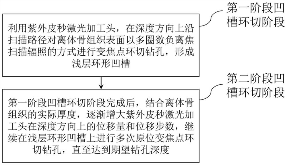
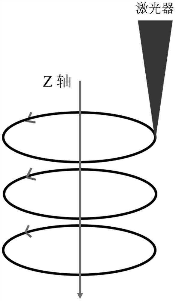
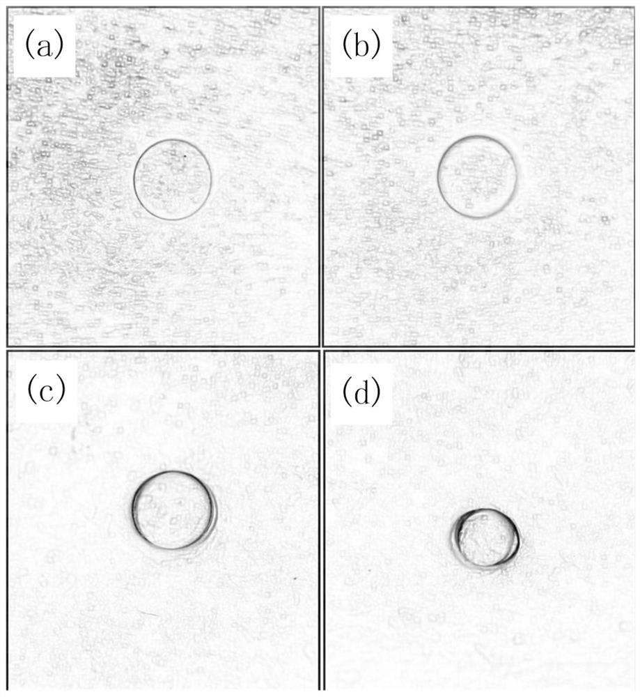
[0033] like image 3As shown in a-3d, the isolated porcine femur from which the soft tissue and periosteum have been removed is drilled. In the case of continuously spraying water on the bone tissue around the drill hole, the average power is first used in the first stage of groove circumcision drilling. 12W, repetition frequency 500KHz, picosecond 355nm UV laser with defocus of -1mm is used for zoom point circumcision drilling, scanning speed is 2000mm / s, number of scanning circles is 500, Z axis displacement is -0.1mm, along Z The number of axial displacement steps is 10. After the circumcision, the appearance of the drilled bone tissue is as attached image 3 As shown in a, the drilling depth measured by confocal at this time is 0.5 mm, and the displacement of the laser head along the z-axis direction is twice the drilling depth.

[0034] After that, the second stage of groove circumcision drilling is carried out in situ, the Z-axis displacement is increased to -0.12mm, an...

Embodiment 2

[0037] like Figure 4 a and Figure 4 As shown in b, drill the isolated porcine femur with soft tissue and periosteum removed. In the case of continuously spraying water on the bone tissue around the drill hole, first use the average power of 6W in the first stage of groove circumcision, and the repetition frequency 500KHz, picosecond 355nm UV laser with defocus of -1mm starts to drill with zoom focus circumcision, scanning speed is 2000mm / s, number of scanning circles is 500, Z axis displacement is -0.1mm, and the number of displacement steps along Z axis is 10, a shallower annular groove is obtained, as attached Figure 4 a is the surface topography of the annular groove. At this time, the drilling depth measured by confocal is 0.56 mm, and the displacement of the laser head along the z-axis direction is 1.78 times the drilling depth.

[0038] Afterwards, the second stage of groove circumcision drilling is carried out in situ, the displacement of the processing head along ...


PUM

PropertyMeasurementUnit
Defocus amountaaaaaaaaaa
Depthaaaaaaaaaa
Depthaaaaaaaaaa

Abstract

The invention discloses a process method for a non-carbonization deep hole on an in-vitro bone drill through ultraviolet picosecond laser variable-focus ring cutting. The process method comprises the following steps of carrying out a first stage of groove ring cutting stage: performing variable-focus ring cutting drilling on the surface of an in-vitro bone tissue along a scanning path in the depth direction by using a ultraviolet picosecond laser processing head in a multi-circle negative out-of-focus scanning irradiation mode, forming a shallow annular groove; and carrying out a second-stage groove ring cutting stage: after the first-stage groove ring cutting stage is completed, combining with the actual thickness of the in-vitro bone tissue, gradually increasing the displacement amount and the displacement step number of the ultraviolet picosecond laser processing head in the depth direction, and continuing to perform in-situ variable-focus ring cutting drilling on the shallow annular groove for multiple times until the expected drilling depth is reached. According to the process method, the problems of bone tissue carbonization and bone strut removal in the deep hole laser bone drill process are solved, the problem of bone tissue carbonization in the deep hole drilling process is effectively solved while the drilling efficiency is guaranteed, and the stability of the required deep hole of the bone drill is guaranteed.

Description

technical field [0001] The invention relates to the technical field of laser bone drilling, in particular to a process method for circumcutting non-carbonized deep holes of ex vivo bone drills with an ultraviolet picosecond laser zoom point. Background technique [0002] At present, the commonly used bone drilling method is mechanical drilling. However, for the through-hole drilling of long bones such as femur and tibia, this mechanical drilling method has a series of problems. For example, due to the large drilling depth, the hardness value of the drilling site changes repeatedly. , the instability, thermal damage and chip removal problems during the drilling process are obvious; when drilling inclined holes with highly curved or irregular surfaces, it is difficult for the drill to achieve balance, the positioning of the drill is difficult, and it is easy to slip; A large amount of mechanical heat energy or the handle of the drill bit is not stable, which may easily cause t...

Claims


Application Information

Patent Timeline
IPC IPC(8): B23K26/382B23K26/082
CPCB23K26/382B23K26/082
Inventor 季凌飞许园波
Owner BEIJING UNIV OF TECH
Why Eureka
Try Eureka