Laminated solar cell and preparation method thereof
A technology for stacking solar cells and batteries, applied in the field of solar cells, can solve the problems of inability to be widely promoted, limited requirements for bottom cell types, and narrow application range of bottom cells, and achieves the effect of simplifying the cell structure and reducing the manufacturing cost.
- Summary
- Abstract
- Description
- Claims
- Application Information
AI Technical Summary
Problems solved by technology
Method used
Image
Examples
preparation example Construction
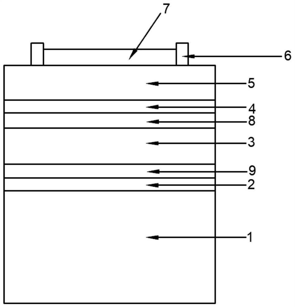
[0081] In another specific embodiment, the present invention provides a preparation method of the above-mentioned tandem solar cell, and the preparation method includes:
[0082] A composite layer 2, a perovskite layer 3, a buffer layer 4, a conductive layer 5, a metal electrode layer and an antireflection layer 6 are sequentially prepared on the surface of the crystalline silicon substrate 1, and a metal electrode 7 is connected to the metal electrode layer.
[0083] Among them, the composite layer 2 is prepared by plasma-enhanced chemical vapor deposition method, atomic layer deposition method, magnetron sputtering method, solution method and thermal evaporation method; the perovskite layer 3 is prepared by spin coating method, spray pyrolysis method, thermal Prepared by evaporation method, blade coating method, coating method or printing method; buffer layer 4 is prepared by atomic deposition method, plasma-enhanced chemical vapor deposition method, spin coating method, sput...
Embodiment 1
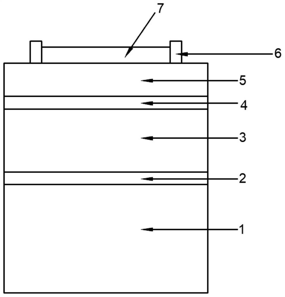
[0085] This embodiment provides a tandem solar cell, and the tandem solar cell such as figure 1 As shown, it includes a crystalline silicon substrate 1, a composite layer 2, a perovskite layer 3, a buffer layer 4, a conductive layer 5, a metal electrode layer and an antireflection layer 6 that are stacked and closely attached in sequence, and the surface of the metal electrode layer is also provided with There are metal electrodes 7 .
[0086] The crystalline silicon substrate 1 is homogeneous crystalline silicon, the thickness of the composite layer 2 is 100 nm, the thickness of the perovskite layer 3 is 500 m, the thickness of the buffer layer 4 is 2 nm, the thickness of the conductive layer 5 is 100 nm, and the thickness of the metal electrode layer is 60 nm, and the thickness of the antireflection layer 6 is 150 nm.
[0087] This embodiment also provides a preparation method of the above-mentioned tandem solar cell, and the preparation method specifically includes the fol...
Embodiment 2
[0095] This embodiment provides a tandem solar cell, and the tandem solar cell such as figure 1 As shown, it includes a crystalline silicon substrate 1, a composite layer 2, a perovskite layer 3, a buffer layer 4, a conductive layer 5, a metal electrode layer and an antireflection layer 6 that are stacked in sequence and closely attached, and the surface of the metal electrode layer is also provided with There are metal electrodes 7 .
[0096] The crystalline silicon substrate 1 is heterogeneous crystalline silicon, the thickness of the composite layer 2 is 50 nm, and the material of the composite layer 2 is nanocrystalline silicon. The thickness of the perovskite layer 3 is 400 nm, and the chemical formula of the perovskite material used in the perovskite layer 3 is CsPbI 3 . The thickness of the buffer layer 4 is 5 nm, and the material of the buffer layer 4 is molybdenum oxide. The thickness of the conductive layer 5 is 150 nm, and the material of the conductive layer 5 i...
PUM
| Property | Measurement | Unit |
|---|---|---|
| thickness | aaaaa | aaaaa |
| thickness | aaaaa | aaaaa |
| thickness | aaaaa | aaaaa |
Abstract
Description
Claims
Application Information
 - R&D
- Intellectual Property
- Life Sciences
- Materials
- Tech Scout
- Unparalleled Data Quality
- Higher Quality Content
- 60% Fewer Hallucinations
Browse by: Latest US Patents, China's latest patents, Technical Efficacy Thesaurus, Application Domain, Technology Topic, Popular Technical Reports.
© 2025 PatSnap. All rights reserved.Legal|Privacy policy|Modern Slavery Act Transparency Statement|Sitemap|About US| Contact US: help@patsnap.com


