
Cell lysis device and cell purification and/or cell lysis method based on cell lysis device

A lysis device and cell technology, applied in cell dissociation methods, biochemical equipment and methods, methods of stress-stimulated microbial growth, etc., can solve the problems of low lysis accuracy, inability to guarantee, and inability to lysis.

Inactive Publication Date: 2021-08-31
SHANGHAI UNIV
View PDF5 Cites 1 Cited by
  • Summary
  • Abstract
  • Description
  • Claims
  • Application Information

AI Technical Summary

Problems solved by technology

However, the production of microarray electrodes is difficult, and the cell growth is not arranged regularly, so it cannot be guaranteed to grow on the microarray electrodes. Impurity cells that are not directly above the microarray electrodes will not be lysed, and the lysis accuracy is low.

Method used


Image

  • Cell lysis device and cell purification and/or cell lysis method based on cell lysis device
  • Cell lysis device and cell purification and/or cell lysis method based on cell lysis device
  • Cell lysis device and cell purification and/or cell lysis method based on cell lysis device

Examples


preparation example Construction

[0019] The microtube electrode 12 is preferably prepared by the following method: using a needle pulling instrument to draw the microtube raw material tube to obtain a microtube;

[0020] Fill the two microtubes with liquid metal, centrifuge to make the liquid metal move to the tip of the microtube; cut off the microtube so that the inner diameter of the tip of the microtube is 4-20 μm. The present invention has no special limitation on the amount of liquid metal to be filled, as long as it can conduct electricity.

[0021] In the present invention, the inner diameter of the tip of the microtube is preferably 5-15 μm, more preferably 10 μm.

[0022] In the present invention, the speed of the centrifugation is preferably 3000r / min-1200r / min (corresponding to 5-15μm); the time of the centrifugation is preferably 2min; the equipment used for the centrifugation is preferably a centrifuge.

[0023] In the present invention, the device for severing the microtube is preferably a sho...

Embodiment 1

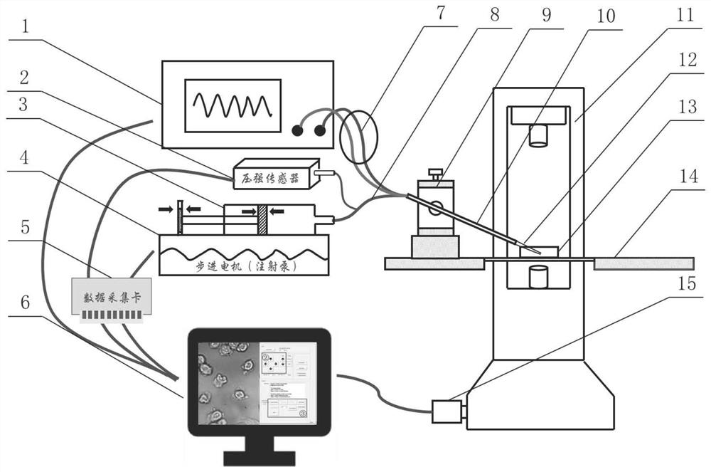
[0054] Such as figure 1 As shown, the cell lysing device of this embodiment consists of a pulse power supply 1, a pressure sensor 2, a syringe pump 3, a stepper motor 4, a data acquisition card 5, a computer 6, a copper wire 7, a microtube channel 8, a mechanical arm 9, a micro Tube frame 10, inverted microscope 11, microtube electrode 12, culture dish (cell sample) 13, mobile stage 14 and camera 15 are composed.

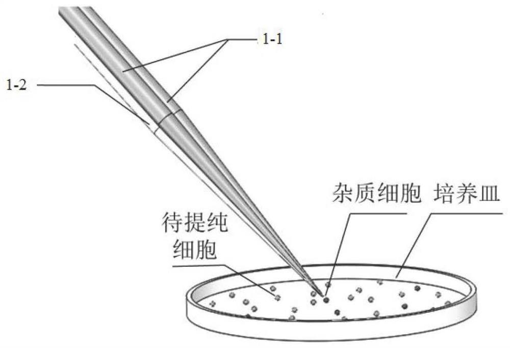
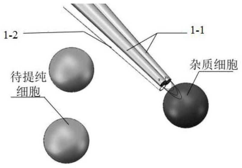
[0055] The whole system is mainly divided into two modules, namely image 3 Impurity cell lysis module, Figure 4 Cell lysate collection module. in image 3 What is realistic is a local schematic diagram of the high-voltage electric field generated by the tip of the microtube electrode during cell lysis. The microtube electrode 12 in this system is composed of three single microtubes, two of which are filled with liquid metal gallium and used as electrodes. The two electrodes are connected to the pulse power supply 1 by a copper wire 7. During lysis, the pulse ...


PUM

PropertyMeasurementUnit
The inside diameter ofaaaaaaaaaa

Abstract

The invention provides a cell lysis device and a cell purification and / or cell lysis method based on the cell lysis device, and belongs to the technical field of cell lysis purification. The cell lysis device comprises a pulse power supply (1) and a microcapillary electrode (12) electrically connected with the pulse power supply (1), and the microcapillary electrode (12) comprises an electrode tube (1-1); and a liquid metal thin film is attached to the inner wall of the electrode tube (1-1). According to the invention, the pulse power supply (1) is controlled to release a voltage, and a non-uniform electric field is formed above impurity cells through the electrode tube (1-1). As the surrounding voltage is far higher than the transmembrane potential of the impurity cells, the impurity cells are rapidly lysed so as to fulfill the aim of lysing the impurity cells.

Description

technical field [0001] The invention relates to the technical field of cell lysis and purification, in particular to a cell lysis device and a cell purification and / or cell lysis method based on the cell lysis device. Background technique [0002] Selective lysis of single cells is a key step in the analysis of rare cells or target populations in complex biological samples such as blood or biopsies. It collects cellular components by destroying intact and complex membrane structures and facilitates the analysis of intracellular components such as DNA , RNA and protein. [0003] The methods currently used for cell lysis mainly include chemical lysis, sonic lysis, electrolysis, and optical lysis. The chemical lysis process requires the use of lysis reagents such as detergents, chaotropic salts, enzymes, and alkalis, which will affect the subsequent analysis of cell fluid molecules. Optical lysis is to use laser micropulses to focus near the target cells, and form cavitation ...

Claims


Application Information

Patent Timeline
IPC IPC(8): C12M1/42C12M1/33C12M1/34C12M1/36C12M1/00C12N5/079
CPCC12M41/40C12M41/48C12M45/07C12N5/062C12N2509/00C12N2529/00
Inventor 刘娜袁惠宇张丹岳涛刘媛媛兰伟霞彭艳蒲华燕谢少荣罗均
Owner SHANGHAI UNIV
Learn More