
MEMS piezoresistive pressure sensor and preparation method thereof

A pressure sensor, piezoresistive technology, applied in fluid pressure measurement by changing ohmic resistance, piezoelectric device/electrostrictive device, piezoelectric/electrostrictive/magnetostrictive device, etc., can solve the difficulty of debugging and compensation Large, easy-to-break beam membrane thickness, large performance differences, etc., to achieve the effect of high cost performance, low compensation difficulty, and improved linearity

Pending Publication Date: 2021-09-03
SHENZHEN MEISI XIANRUI ELECTRONICS CO LTD
View PDF0 Cites 1 Cited by
  • Summary
  • Abstract
  • Description
  • Claims
  • Application Information

AI Technical Summary

Problems solved by technology

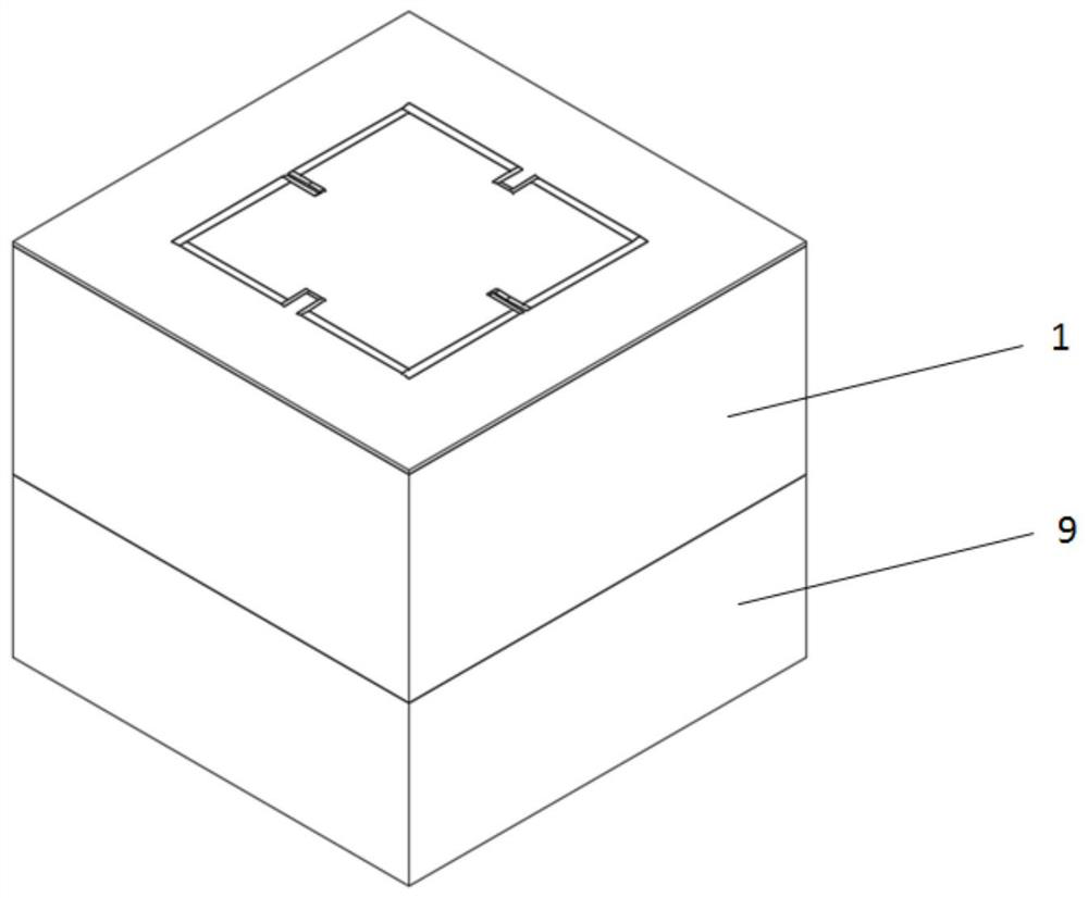
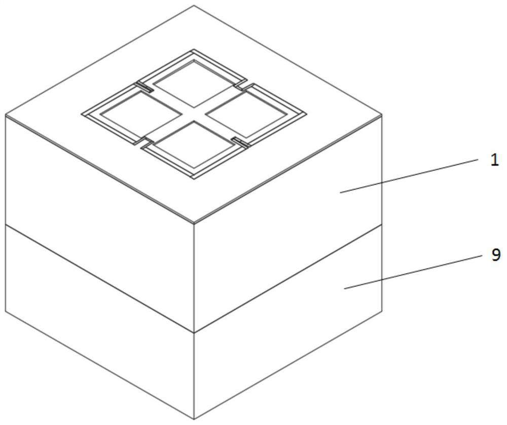
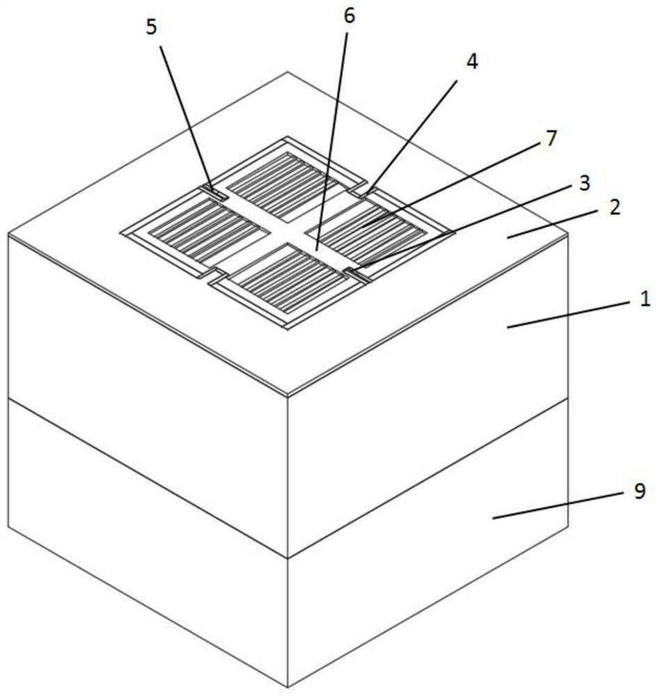
[0004] In order to solve the above problems, the object of the present invention is to provide a MEMS piezoresistive pressure sensor, which solves the performance problems caused by the poor linearity, easy fragmentation and uneven beam membrane thickness of the MEMS piezoresistive pressure sensor in the prior art. Problems with large differences and difficulty in later debugging and compensation

Method used


Image

  • MEMS piezoresistive pressure sensor and preparation method thereof
  • MEMS piezoresistive pressure sensor and preparation method thereof
  • MEMS piezoresistive pressure sensor and preparation method thereof

Examples


preparation example Construction

[0058] The embodiment of the present invention also provides a preparation method of the MEMS piezoresistive pressure sensor with the grating tooth structure described in Embodiment 1, the method specifically includes the following steps:

[0059] S1. Fabricate interconnected varistors and heavily doped contact regions on the front side of the silicon substrate;

[0060] S2. Making lead holes and metal leads on the front side of the silicon substrate;

[0061] S3, making a beam membrane structure on the front side of the silicon substrate by photolithography;

[0062] S4. Fabricate a grid tooth structure by photolithography in the non-cross beam region on the front side of the silicon substrate;

[0063] S5. Carry out back cavity etching on the back side of the silicon substrate until the appropriate thickness is stopped, and form a silicon strained film with a gate tooth structure;

[0064] S6. Bonding the strained silicon film with grid teeth structure obtained in S5 to gl...


PUM


Abstract

The invention discloses an MEMS piezoresistive pressure sensor and a preparation method thereof, and the pressure sensor comprises a silicon strain film with a grid tooth structure and a beam film structure, a piezoresistor, a heavily doped contact region, a metal lead, and a glass pedestal. The silicon strain film is a silicon film which is formed by etching the front surface of the silicon substrate and performing a back cavity corrosion process on the back surface of the silicon substrate and is provided with a front beam film and a back cavity structure, the grid tooth structure is positioned on the front surface of the silicon strain film, the piezoresistor is positioned at the end part of the grid tooth structure, and the metal lead and the heavily doped contact region form ohmic contact on the front surface of the silicon strain film; and the glass base is perforated glass bonded with the back surface of the silicon strain film. The piezoresistive pressure sensor is formed by arranging the silicon strain film with the grid tooth structure and the beam film structure, the piezoresistor, the heavily doped contact region, the metal lead and the glass base on the front surface of the silicon substrate, so the grid tooth beam film structure can improve the linearity of the sensor while ensuring the sensitivity of the pressure sensor.

Description

technical field [0001] The invention belongs to the technical field of microelectromechanical system sensors, and in particular relates to a MEMS piezoresistive pressure sensor and a preparation method thereof. Background technique [0002] The MEMS piezoresistive pressure sensor is based on the piezoresistive effect of single crystal silicon to convert the external pressure change into a corresponding electrical signal, and realizes the measurement of the external pressure by forming a Wheatstone bridge with four equivalent resistances. MEMS piezoresistive pressure sensors are mainly used in related fields such as industrial control, automotive electronics, consumer electronics, medical electronics, and aerospace. The MEMS piezoresistive pressure sensor adopts MEMS technology for design and process development. It uses silicon diaphragms obtained from silicon wafers as force-sensing elements, and four pairs of equivalent resistance and low It is composed of a multi-functio...

Claims


Application Information

Patent Timeline
IPC IPC(8): G01L1/22G01L9/04B81B3/00B81C1/00
CPCG01L1/2293G01L9/04B81B3/00B81C1/00158
Inventor 武斌许克宇
Owner SHENZHEN MEISI XIANRUI ELECTRONICS CO LTD
Learn More