
Flue gas waste heat recycling system and method

A flue gas waste heat and flue gas technology, applied in heating systems, hot water central heating systems, heating methods, etc., to achieve the effects of reducing energy consumption, improving recycling efficiency, and improving heat energy utilization

Pending Publication Date: 2021-11-02
吉林宏日新能源股份有限公司
View PDF0 Cites 3 Cited by
  • Summary
  • Abstract
  • Description
  • Claims
  • Application Information

AI Technical Summary

Problems solved by technology

[0004] The technical problem to be solved by the present invention is to overcome the deficiencies of the prior art and provide a waste heat recovery system for flue gas. Aiming at the problem that the energy efficiency of the existing absorption heat pump technology is too low when the heat source temperature is low, combined with the biomass flue gas waste heat energy level Distribution characteristics, build a multi-stage, multi-stage heat pump cycle process driven by waste heat of medium and low temperature flue gas and adopt efficient mass transfer and heat transfer technology

Method used


Image

  • Flue gas waste heat recycling system and method
  • Flue gas waste heat recycling system and method
  • Flue gas waste heat recycling system and method

Examples


Embodiment Construction

[0026] A schematic diagram of a layer structure according to an embodiment of the invention is shown in the drawing. The figures are not drawn to scale, with certain details exaggerated and possibly omitted for clarity. The shapes of the various regions and layers shown in the figure, as well as their relative sizes and positional relationships are only exemplary, and may deviate due to manufacturing tolerances or technical limitations in practice, and those skilled in the art will Regions / layers with different shapes, sizes, and relative positions can be additionally designed as needed.

[0027] Apparently, the described embodiments are some, but not all, embodiments of the present invention. Based on the embodiments of the present invention, all other embodiments obtained by persons of ordinary skill in the art without making creative efforts belong to the protection scope of the present invention. In the description of the present invention, it should be noted that the te...


PUM


Abstract

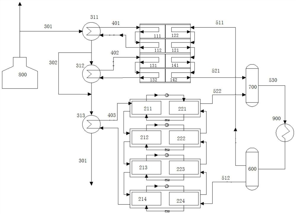
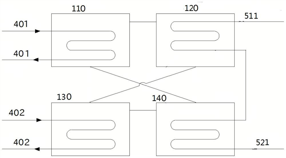
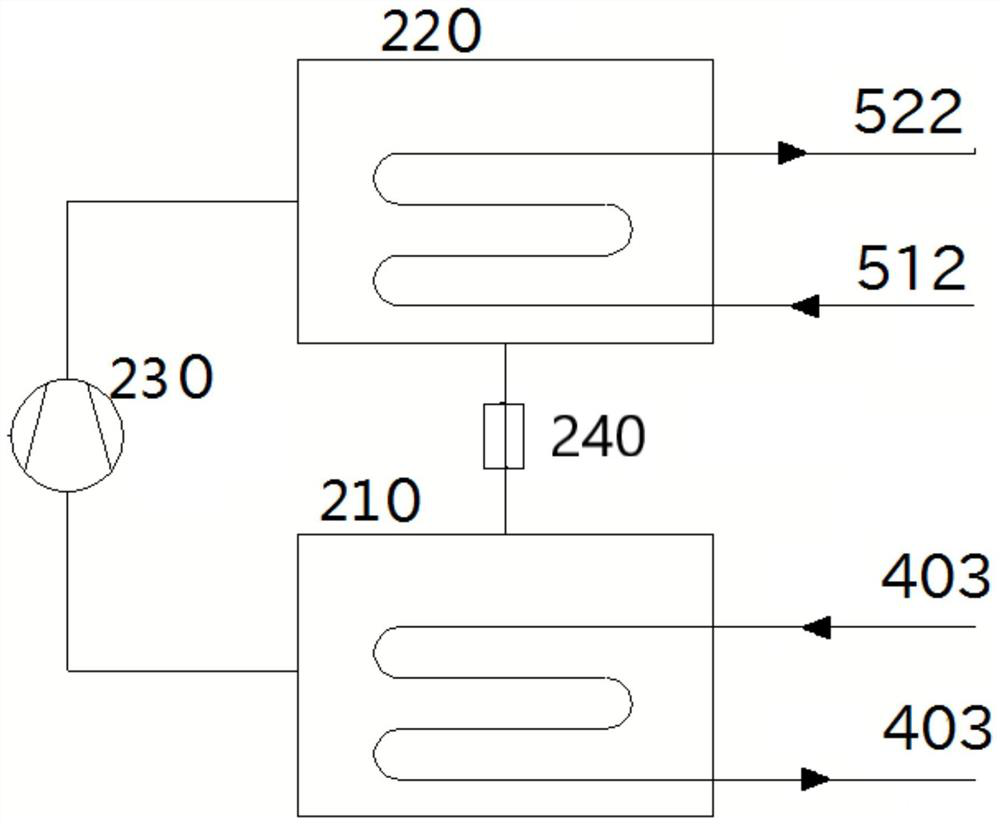
The invention discloses a flue gas waste heat recycling system comprising a smoke exhaust pipe (301), flue gas sequentially enters a first-stage heat exchanger (311), a second-stage heat exchanger (312) and a third-stage heat exchanger (313) through the smoke exhaust pipe to release heat, and first-stage waste heat water in a first-stage waste heat water circulating pipe (401), second-stage waste heat water in a second-stage waste heat water circulating pipe (402) and third-stage waste heat water in a third-stage waste heat water circulating pipe (403) are heated correspondingly; the first-stage waste heat water enters an absorption heat pump generator (110) for cooling through the first-stage waste heat water circulating pipe, the second-stage waste heat water enters an absorption heat pump evaporator (130) for cooling through the second-stage waste heat water circulating pipe, and the third-stage waste heat water enters a compression heat pump evaporator (210) for cooling through the third-stage waste heat water circulating pipe; and heat supply network water sequentially enters an absorption heat pump to be heated through a first heat supply network water return pipe (511), and the heat supply network water further enters a compression heat pump to be heated through a second heat supply network water return pipe (512). The flue gas waste heat energy is utilized in a gradient mode, and heat is recycled more sufficiently.

Description

technical field [0001] The invention belongs to the technical field of heat energy recovery, in particular to a flue gas waste heat recovery system and method. Background technique [0002] In recent years, more and more attention has been paid to the consumption and utilization of biomass, but the water content of biomass raw materials is relatively high, the exhaust gas temperature of conventional biomass cogeneration units is about 145°C, and the sensible heat loss in exhaust waste heat accounts for the low calorific value of fuel. The latent heat loss is about 2 times of the sensible heat loss, which makes the thermal efficiency of the biomass combined heat and power unit relatively low, and the comprehensive utilization rate of energy is low. If the flue gas temperature is lowered below the dew point, the flue gas can release a large amount of latent heat, which significantly improves the efficiency of waste heat recovery. Therefore, the waste heat recovery technology ...

Claims


Application Information

Patent Timeline
Patent Type & Authority Applications(China)
IPC IPC(8): F24D3/18F24D3/10F23J15/06
CPCF24D3/18F24D3/10F23J15/06F24D2200/123F24D2200/126F24D2200/18Y02E20/30
Inventor 洪浩王震坤隋海然田晓霞张志鑫陈壹杰刘菲许雪楠冯雨
Owner 吉林宏日新能源股份有限公司
Learn More