Flue gas waste heat recovery system of biomass boiler

A biomass boiler, flue gas waste heat technology, applied in the directions of preheating, steam generation, liquid degassing, etc., can solve the problems affecting the safe operation of equipment, can not meet the boiler energy saving, air preheater cold end corrosion, etc., and achieve good heat conduction. performance, reducing equipment investment and operating costs, and the effect of high tensile strength of welds

Active Publication Date: 2021-11-12
POWERCHINA HEBEI ELECTRIC POWER SURVEY & DESIGN INST CO LTD
View PDF5 Cites 0 Cited by
  • Summary
  • Abstract
  • Description
  • Claims
  • Application Information

AI Technical Summary

Problems solved by technology

[0002] In the process of thermal power generation, in the existing biomass combustion boilers, steam is generated by fully burning biomass combustion particles. During the combustion process, a large amount of high-temperature flue gas released will be discharged naturally, which not only pollutes the environment, but also It causes waste and cannot meet the requirements for boiler energy saving; at present, the waste heat utilization system of flue gas at the tail of conventional biomass boilers is as follows: figure 2 As shown, the flue gas enters the economizer to heat the feed water, and after cooling down, enters the air preheater to heat the cold air
[0003] Due to the chlorine element contained in the biomass, the flue gas is highly corrosive, such as figure 2 In the conventional flue gas waste heat recovery system shown, the temperature of the cold air entering the air preheater is between -10°C and 30°C. If the temperature is too low, it will easily cause condensation of the flue gas, which will further cause corrosion at the cold end of the air preheater and affect the safe operation of the equipment.

Method used


Image

  • Flue gas waste heat recovery system of biomass boiler
  • Flue gas waste heat recovery system of biomass boiler
  • Flue gas waste heat recovery system of biomass boiler

Examples


Embodiment Construction

[0033] Below in conjunction with accompanying drawing, the present invention is described in further detail:

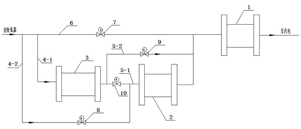
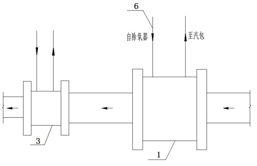
[0034] Such as figure 1 As shown, a biomass boiler flue gas waste heat recovery system includes an economizer 1 connected to the flue gas pipeline, a smoke cooler 2 connected to the economizer, and an air preheater 3 connected to the air pipeline and high-pressure feed water piping from the deaerator;

[0035] The system adds a smoke cooler 2 between the economizer 1 and the air preheater 3, and the preheating of the air does not use flue gas, but is realized by heating the high-pressure feed water from the deaerator to heat the feed water of the air preheater 3 Lead out directly from the high-pressure water supply pipe, preheat the air entering the air preheater 3, then enter the smoke cooler 2 to absorb the heat of the flue gas, and finally return to the high-pressure water supply pipe to enter the economizer 1, and finally enter the steam drum.

[0036] specific...


PUM


Abstract

The invention discloses a flue gas waste heat recovery system of a biomass boiler, and belongs to the technical field of energy recycling. The system comprises an economizer communicating with a flue gas pipeline, a smoke cooler communicating with the economizer, an air preheater communicating with an air pipeline, and a high-pressure water supply pipeline from a deaerator. According to the system, the smoke cooler is additionally arranged between the economizer and the air preheater, and air is preheated by high-pressure feed water from the deaerator other than flue gas; the feed water for heating the air preheater is directly led out from the high-pressure water supply pipeline to preheat the air entering the air preheater, and used for preheating the air entering the air preheater; then, the feed water enters the smoke cooler to absorb the flue gas heat; and finally, the feed water returns to the high-pressure water supply pipeline, enters the economizer and finally enters a steam pocket. According to the flue gas waste heat recovery system, the air preheater can be prevented from being corroded, safe operation of the air preheater is guaranteed, and meanwhile the problem of corrosion of the heating surface at the tail of the boiler can be further solved.

Description

technical field [0001] The invention relates to the technical field of energy recovery and utilization, in particular to a biomass boiler flue gas waste heat recovery system, which is used for thermal power generation biomass boiler flue gas waste heat recovery. Background technique [0002] In the process of thermal power generation, in the existing biomass combustion boilers, steam is generated by fully burning biomass combustion particles. During the combustion process, a large amount of high-temperature flue gas released will be discharged naturally, which not only pollutes the environment, but also It causes waste and cannot meet the requirements for boiler energy saving; at present, the waste heat utilization system of flue gas at the tail of conventional biomass boilers is as follows: figure 2 As shown, the flue gas enters the economizer to heat the feed water, and after cooling down, enters the air preheater to heat the cold air. [0003] Due to the chlorine element...

Claims


Application Information

Patent Timeline
Patent Type & Authority Applications(China)
IPC IPC(8): F22D1/50F23J15/00F23J15/06F23L15/04F28F1/30
CPCF22D1/50F23J15/006F23J15/06F23L15/045F28F1/30Y02E20/34
Inventor 马盟赵剑剑赵华强赵奕萌陈圆圆
Owner POWERCHINA HEBEI ELECTRIC POWER SURVEY & DESIGN INST CO LTD
Why Eureka
Try Eureka