Flue gas treatment process and treatment system

A flue gas treatment and process technology, which is applied in the field of chain grate machine-rotary kiln flue gas treatment, can solve the problems of increased NOx content, difficulty in achieving denitrification and precise control of NOx emission standards, so as to reduce ammonia escape and improve high temperature denitrification efficiency , Optimizing the effect of denitrification process parameters

Active Publication Date: 2022-01-11
ZHONGYE-CHANGTIAN INT ENG CO LTD
View PDF8 Cites 6 Cited by
  • Summary
  • Abstract
  • Description
  • Claims
  • Application Information

AI Technical Summary

Problems solved by technology

However, often due to the cross air problem caused by the difference in temperature and air pressure between the PH section and the TPH section in the chain grate machine production system, that is, the high NOx exhaust gas in the PH section crosses the air to the TPH section, which makes the NOx content in the flue gas in the TPH section increase.
It is difficult to achieve precise denitrification control and NOx emission standards

Method used


Image

  • Flue gas treatment process and treatment system
  • Flue gas treatment process and treatment system
  • Flue gas treatment process and treatment system

Examples


Embodiment 1

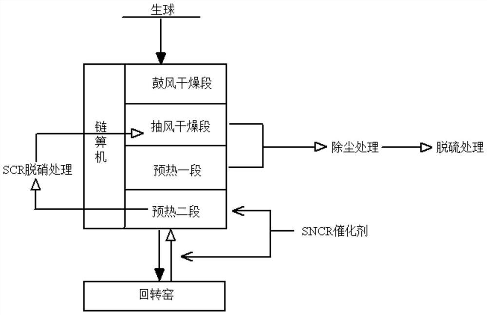
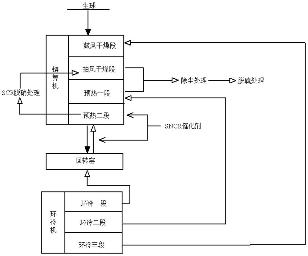
[0360] Such as Figure 6-13 As shown, a flue gas treatment system includes a chain grate machine 1, a rotary kiln 2, a desulfurization device 4, an SCR denitrification device 5, and a dust removal device 6. According to the direction of the material, the chain grate machine 1 is sequentially provided with a blast drying section UDD, a draft drying section DDD, a preheating section TPH and a preheating section PH. The second stage of preheating PH communicates with the flue gas outlet of the rotary kiln 2 through the first pipeline L1. An SNCR denitrification device 8 is installed in the second preheating stage PH and / or the first pipeline L1. The air outlet of the second preheating stage PH is connected to the air inlet of the draft drying stage DDD through the fourth pipeline L4. The air outlet of the exhausting and drying section DDD is connected to the chimney through the fifth pipeline L5. The SCR denitration device 5 is arranged on the fourth pipeline L4. The desulfur...

Embodiment 2

[0362] Repeat Example 1, except that an anti-blow-by wind device 3 is arranged between the first stage of preheating TPH and the second stage of preheating PH.

Embodiment 3

[0364] Embodiment 2 is repeated, except that the anti-channeling device 3 includes an airflow balance plate 301 , a moving platform 302 , rollers 303 and slots 304 . The airflow balance plate 301 is arranged inside the chain grate machine 1 . The mobile platform 302 is arranged on both sides of the outer lower end of the first-stage preheating PH and the second-stage preheating PH. The rollers 303 are arranged at the bottom of the mobile platform 302 . The slots 304 are arranged on both sides of the outer upper ends of the first-stage preheating PH and the second-stage preheating PH. The mobile platform 302 is also provided with a fixed base 30201 . A column 30202 is arranged on the fixing base 30201 . The top of the column 30202 passes through the slot 304 and connects with the top of the airflow balance plate 301 . A mobile motor 30203 is also provided outside the mobile platform 302 . The mobile motor 30203 drives the mobile platform 302 to move on the rollers 303 . T...


PUM

PropertyMeasurementUnit
thicknessaaaaaaaaaa
thermal stabilityaaaaaaaaaa
thicknessaaaaaaaaaa

Abstract

The invention discloses a chain grate-rotary kiln flue gas treatment process and treatment system. A control method of an SNCR-SCR coupling denitration system is adopted, a composite additive is added into an SNCR denitration catalyst or a novel SNCR composite ammonia agent is provided; and meanwhile, a movable airflow balance plate is additionally arranged between a PH section and a TPH section of a chain grate, the air pressure of the TPH section is controlled to be larger than or equal to the air pressure of the PH section by utilizing the position change of the airflow balance plate, so that the problem that the content of NOx in flue gas of the TPH section is increased due to the fact that high-NOx-content waste gas of the PH section flees towards the TPH section is prevented. The optimal coupling ultralow NOx emission technology can be formed, the denitration efficiency can be effectively guaranteed on the premise that SNCR ammonia consumption is reduced, meanwhile, the service lifetime of an SCR denitration catalyst can be prolonged, and the denitration operation cost and investment cost of the system are obviously reduced. The utilization efficiency of a flue gas denitration reducing agent is further improved, and the escape amount of NH3 is reduced.

Description

technical field [0001] The invention relates to flue gas treatment engineering, in particular to a chain grate machine-rotary kiln flue gas treatment process and method, and belongs to the technical field of chain grate machine-rotary kiln flue gas treatment. Background technique [0002] The National Guidance Catalog for Industrial Structure Adjustment (2019 Edition) clearly states that the encouraged technologies include blast furnace high-proportion pellet smelting technology, because the pellet production process has low energy consumption, relatively friendly environment, and the products have good strength, high grade, metallurgical With the advantages of good performance, when applied to blast furnace smelting, it can increase production and save coke, improve ironmaking technical and economic indicators, reduce pig iron cost, and improve economic benefits. From 2015 to 2018, my country's pellet production increased from 128 million tons to 159 million tons. my count...

Claims


Application Information

Patent Timeline
Patent Type & Authority Applications(China)
IPC IPC(8): B01D53/56B01D53/86B01D53/34B01D53/75B01D53/00
CPCB01D53/56B01D53/8628B01D53/346B01D53/75B01D53/00B01D53/343B01D2258/0283B01D2251/2062B01D2251/2067B01D2257/30B01D53/86B01D53/34C22B1/20C22B1/216B01D53/90
Inventor 胡兵叶恒棣魏进超陈红刘昌齐代友训王兆才杨本涛刘臣师本敬
Owner ZHONGYE-CHANGTIAN INT ENG CO LTD
Why Eureka
Try Eureka