Large-cylinder-diameter gas engine turbulent jet ignition system, gas supply system and method

A gas engine, turbulent jet technology, applied in gaseous engine fuels, combustion engines, engine components, etc., can solve the problems of poor combustion stability, engine ignition, and high concentration of residual combustion exhaust gas, and achieve improved ignition capability, increased ignition energy, and shortened The effect of flame spread distance

Active Publication Date: 2022-01-28
SHANDONG UNIV
View PDF7 Cites 9 Cited by
  • Summary
  • Abstract
  • Description
  • Claims
  • Application Information

AI Technical Summary

Problems solved by technology

[0005] In order to solve the above problems, the present invention proposes a turbulent jet ignition system, gas supply system and method for a gas engine with a large bore. Lean combustion of gas engines solves the problems of high concentration of combustion residual exhaust gas in the pre-combustion chamber and poor ignition and combustion stability of the engine

Method used


Image

  • Large-cylinder-diameter gas engine turbulent jet ignition system, gas supply system and method
  • Large-cylinder-diameter gas engine turbulent jet ignition system, gas supply system and method
  • Large-cylinder-diameter gas engine turbulent jet ignition system, gas supply system and method

Examples


Embodiment 1

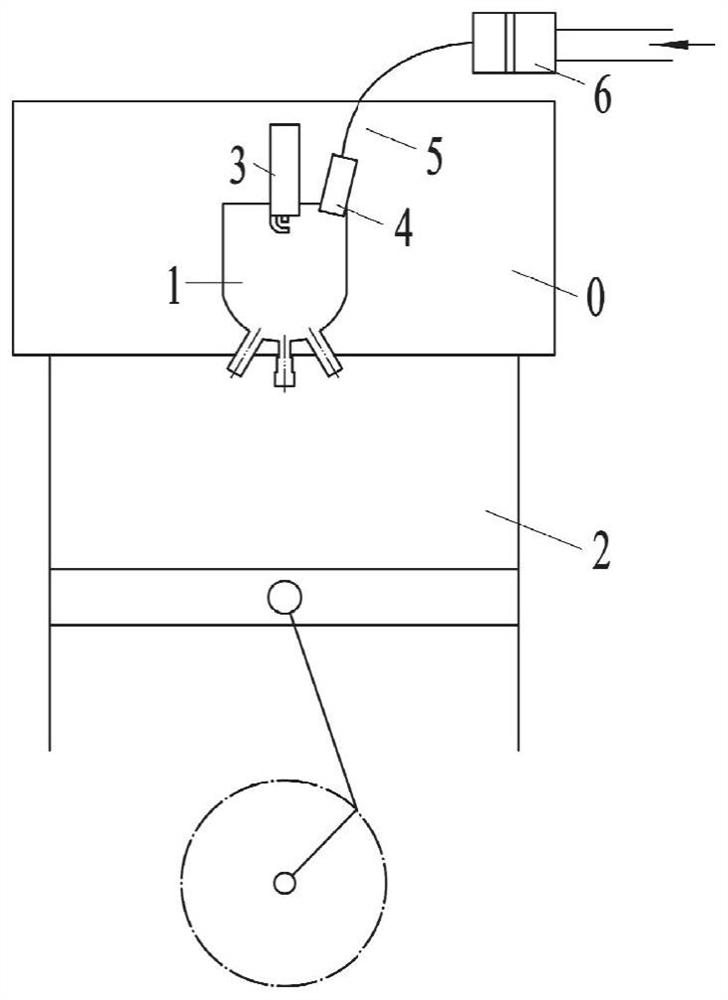
[0044] In one or more embodiments, a turbulent jet ignition system for a large bore gas engine is disclosed, such asfigure 1 shown, including:

[0045] a pre-combustion chamber 1, the pre-combustion chamber 1 is respectively communicated with the main combustion chamber 2 through a plurality of fluid passages;

[0046] The pre-combustion chamber gas injection valve 6 is connected to the pre-combustion chamber 1 through the gas delivery pipeline 5 and the one-way valve 4, and is used to inject auxiliary gas into the pre-combustion chamber 1 in a timed and quantitative manner;

[0047] The spark plug 3 is arranged on the pre-combustion chamber 1 , and the ignition electrode of the spark plug 3 is inserted into the pre-combustion chamber 1 for igniting the combustible mixture in the pre-combustion chamber 1 .

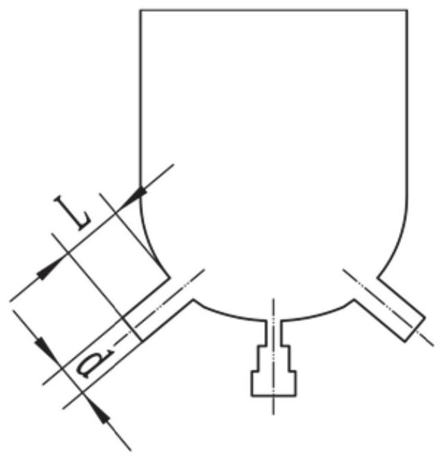
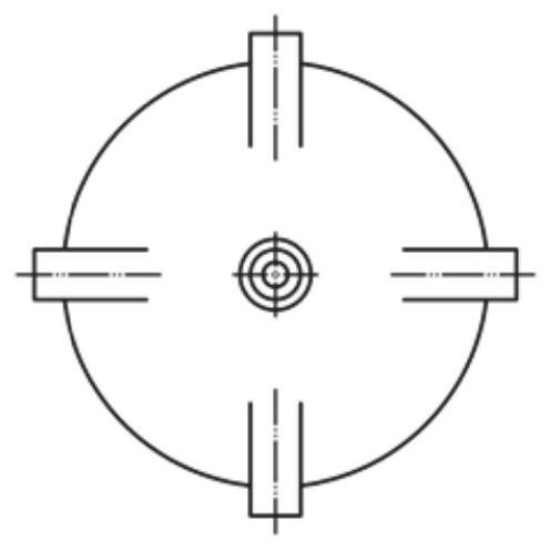
[0048] At least one fluid passage is provided at the bottom center of the pre-chamber 1 , and the central axis of the fluid passage is parallel to the central axis of the ...

Embodiment 2

[0056] In one or more embodiments, an air supply system for a large bore gas engine is disclosed, incorporating Figure 4 , including: the controller 20 and the turbulent jet ignition system of the large-bore gas engine described in the first embodiment; the main combustion chamber 2 is provided with an intake passage 16 and an exhaust passage 19 respectively, and the intake passage 16 passes through the pre-combustion chamber gas. The injection valve 6 is connected with the gas delivery pipeline 5; the intake passage 16 is connected with the gas intake passage; the intake passage 16 is also connected with the supercharger through the intercooler 15; The supercharger is connected; the controller 20 is used to control the pre-combustion chamber gas injection valve 6, the exhaust bypass valve 14 and the gas intake passage.

[0057] Specifically, the intake passage 16 and the exhaust passage 19 are connected with the main combustion chamber 2 to organize the intake and exhaust of...

Embodiment 3

[0064] In one or more embodiments, a gas supply method for a large bore gas engine is disclosed, the method comprising the following processes:

[0065] Control the gas intake passage to be closed, and control the air to enter the main combustion chamber 2 and the pre-combustion chamber 1 at the set pressure for scavenging;

[0066] The gas inlet passage is controlled to open, and the gas and air are controlled to enter the inlet passage 16 of the main combustion chamber 2 at a set pressure to form a mixture with a set concentration; the mixture is controlled to enter the main combustion chamber 2 and pre-combustion respectively. room 1;

[0067] The gas injection pressure is reduced, and the pre-combustion chamber gas injection valve 6 is closed, so that the gas concentration of the mixture in the intake passage 16 is reduced and only enters the main combustion chamber 2 to complete the set gas injection amount and air intake amount.

[0068] The specific method steps are as...


PUM


Abstract

The invention discloses a large-cylinder-diameter gas engine turbulent jet ignition system, a gas supply system and method, and the turbulent jet ignition system comprises a pre-combustion chamber which forms a spatial umbrella-shaped distributed ignition source in a main combustion chamber through a plurality of fluid passages; a sparking plug which is arranged on the pre-combustion chamber and used for igniting mixed gas in the pre-combustion chamber; a pre-combustion chamber gas injection valve which is connected with the pre-combustion chamber through a gas conveying pipeline and a one-way valve and used for injecting auxiliary gas into the pre-combustion chamber in a timed and quantitative mode. The gas supply system comprises a controller and the turbulent jet ignition system, and the controller is used for controlling gas supply of the pre-combustion chamber and fuel supply of the gas inlet channel of the main combustion chamber. Accurate stratified combustion can be formed between the pre-combustion chamber and the main combustion chamber; turbulent jet flow generated by mixed combustion in the pre-combustion chamber can form umbrella-shaped ignition source distribution in the main combustion chamber, the flame propagation distance is effectively shortened, and the combustion speed of mixed gas in the main combustion chamber is increased.

Description

technical field [0001] The invention relates to the technical field of large-bore gas engines, in particular to a turbulent jet ignition system, an air supply system and a method for a large-bore gas engine. Background technique [0002] The statements in this section merely provide background information related to the present invention and do not necessarily constitute prior art. [0003] The large-bore gas engine with a cylinder diameter greater than 180mm uses natural gas as fuel, and its application fields include inland ship power, oil drilling power and gas generator sets, etc. It is a model with broad application potential. In order to improve the combustion thermal efficiency of the engine and reduce the emission of nitrogen oxides, the technical route of organizing lean combustion in the cylinder is proposed. However, the slow flame propagation speed of natural gas, poor lean burn characteristics, and long flame propagation distance in the combustion chamber of la...

Claims


Application Information

Patent Timeline
Patent Type & Authority Applications(China)
IPC IPC(8): F02B19/00F02B43/10
CPCF02B19/00F02B43/10F02B2043/103Y02T10/30
Inventor 程勇杨雪王鹏程王永启
Owner SHANDONG UNIV
Why Eureka
Try Eureka