Near-zero-emission productization recovery method and system for cleaning nitrogen-rich organic tail gas of electrolyte equipment

A near-zero emission and recovery method technology, applied in chemical instruments and methods, separation methods, gas treatment, etc., can solve problems such as pollution, high cost, and difficulty, and achieve low condensation costs, reduce condensation costs, and increase oil concentration Effect

Pending Publication Date: 2022-02-15
DALIAN UNIV OF TECH PANJIN INST OF IND TECH
View PDF11 Cites 0 Cited by
  • Summary
  • Abstract
  • Description
  • Claims
  • Application Information

AI Technical Summary

Problems solved by technology

The direct discharge of these organic tail gases not only causes a lot of waste of nitrogen resources but also pollutes the environment
[0004] In the prior art, adsorbent adsorption or condensation + membrane separation process is usually used to treat the electrolyte tank to clean nitrogen-rich organic tail gas; however, the organic tail gas is separated by adsorbent adsorption method, and it is difficult to effectively desorb the oil components in the tail gas after adsorption. High cost; and due to the high concentration of nitrogen in the organic tail gas, it is difficult to condense the oil components in the tail gas at room temperature or higher than the room temperature. When the condensation + membrane separation process is used, it is necessary to use propane and other refrigerants in the condensation process, and the cost is high.

Method used


Image

  • Near-zero-emission productization recovery method and system for cleaning nitrogen-rich organic tail gas of electrolyte equipment

Examples


Embodiment 1

[0082] Select porosity 60~80%, the porous polysquintimide of 0.3~0.6um and polycarbonate are support membrane; Use fluorine-containing polysiloxane (molecular weight M w =300000~600000) and solvent ethyl acetate, prepare a coating solution with a concentration of 15%, add a crosslinking agent hydrogen-containing silicone oil and a catalyst platinum complex to it, the concentrations are 2wt% and 0.15wt%, and stir evenly After that, let it stand until there are no bubbles by visual inspection.

[0083] The film liquid is coated on the porous polysquintimide and the polycarbonate support film respectively by one-step roller coating method; the crosslinking temperature of the oven is controlled at 70-80°C, and the first film is obtained by heating and curing until dry without residual solvent. Separation membrane for membrane separation and second membrane separation;

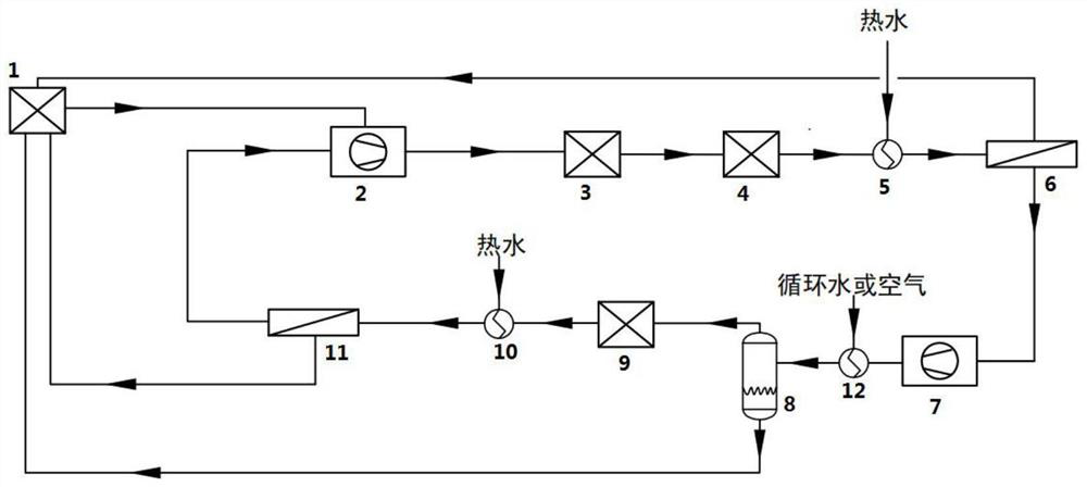
[0084] use figure 1 In the system shown, the electrolyte tank 1 is cleaned with nitrogen-rich organic tail gas...

Embodiment 2

[0089] Select porosity 60~80%, the porous polysquintimide of 0.3~0.6um and polycarbonate are support membrane; Use fluorine-containing polysiloxane (molecular weight M w =300000~600000) and solvent ethyl acetate, prepare a coating solution with a concentration of 15%, add a crosslinking agent hydrogen-containing silicone oil and a catalyst platinum complex to it, the concentrations are 2wt% and 0.15wt%, and stir evenly After that, let it stand until there are no bubbles by visual inspection.

[0090] The film solution is coated on the porous polyimide and polycarbonate support film respectively by one-step roller coating method; the crosslinking temperature of the oven is controlled at 70-80 °C, and the first film is obtained by heating and curing until dry without residual solvent. Separation membrane for membrane separation and second membrane separation;

[0091] use figure 1 In the system shown, the electrolyte tank 1 is cleaned with nitrogen-rich organic tail gas (40°C,...


PUM

PropertyMeasurementUnit
pore sizeaaaaaaaaaa
percent by volumeaaaaaaaaaa

Abstract

The invention belongs to the technical field of tail gas treatment, and particularly relates to a near-zero-emission productization recovery method and system for cleaning nitrogen-rich organic tail gas of electrolyte equipment. The near-zero emission recovery method provided by the invention comprises the following steps: mixing electrolyte equipment cleaning nitrogen-rich organic tail gas and recycle gas of a recovery system, and then carrying out first membrane separation to obtain first-stage retentate gas and first-stage permeate gas; condensing the first-stage permeate gas to obtain condensed gas and condensed liquid, wherein the condensation temperature is greater than or equal to 25 DEG C; and subjecting the condensed gas to second membrane separation, and obtaining second-stage retentate gas and second-stage permeate gas, wherein the second-stage permeate gas is circulation gas. According to the near-zero emission recovery method provided by the invention, nitrogen in the organic tail gas can be recovered under the condition of room temperature, so that the nitrogen meets the requirement of purge gas for cyclic utilization, meanwhile, grease in the organic tail gas is recovered as a cleaning agent for cyclic utilization, and low-cost near-zero-emission productization recovery and cyclic utilization of the electrolyte equipment cleaning nitrogen-rich organic tail gas are realized.

Description

technical field [0001] The invention belongs to the technical field of tail gas treatment, and in particular relates to a near-zero-emission product recovery method and system for cleaning nitrogen-rich organic tail gas by electrolyte equipment. Background technique [0002] With the rapid development of the new energy battery industry, the demand for battery electrolyte has increased on a large scale. The demand for devices for producing electrolyte and electrolyte barrels for packaging electrolyte has also increased. The electrolyte has extremely high requirements on the quality of the production equipment and the electrolyte barrel, and the impurity requirement is at the level of parts per million (ie ppm level). Therefore, in order to achieve the purpose of recycling the electrolyte production device and the electrolyte tank while ensuring the quality of the electrolyte, the electrolyte production device and the electrolyte tank must be cleaned to reduce the impurity co...

Claims


Application Information

Patent Timeline
Patent Type & Authority Applications(China)
IPC IPC(8): B01D53/22B01D53/00B01D46/62
CPCB01D53/226B01D53/005B01D53/002B01D2256/10
Inventor 郭明刚贺高红杨晓航米盼盼代岩阮雪华
Owner DALIAN UNIV OF TECH PANJIN INST OF IND TECH
Why Eureka
Try Eureka