Decoupling type carbon dioxide mineralization membrane electrolysis system for producing high-purity carbonate

A technology of carbonate and membrane electrolysis, applied in the field of electrochemistry, can solve problems such as difficult stable operation of the system, influence on system stability, attenuation, etc., and achieve the effect of continuous stable operation, low cost, and high resource conversion rate

Active Publication Date: 2022-04-15
SICHUAN UNIV
View PDF5 Cites 0 Cited by
  • Summary
  • Abstract
  • Description
  • Claims
  • Application Information

AI Technical Summary

Problems solved by technology

Among them, using cycle H 2 A major difficulty is that the H 2 The electrochemical oxidation reaction requires the use of gas diffusion electrodes, and the difficult-to-control three-phase reaction interface will easily cause the electrode to "flood" and cause the electrode failure reaction to be difficult to operate stably.
And adopting a big core difficult problem of organic PCET reactant is that O 2 Impact on System Stability
Especially absorbing CO 2 on the cathode side, a small amount of O 2 The presence of (gas oxygen or dissolved oxygen) will cause the rapid attenuation of electrochemical proton-coupled electron transfer reactants, making it difficult for the system to operate stably
In addition, CO 2 The mineralized membrane electrolysis system needs to use acidic anolyte to directly treat natural minerals or alkaline solid waste. If PCET reactants are used as electrochemical redox carriers, it will cause irreversible loss of organic PCET reactants and increase treatment costs.

Method used


Image

  • Decoupling type carbon dioxide mineralization membrane electrolysis system for producing high-purity carbonate
  • Decoupling type carbon dioxide mineralization membrane electrolysis system for producing high-purity carbonate
  • Decoupling type carbon dioxide mineralization membrane electrolysis system for producing high-purity carbonate

Examples


Embodiment 1

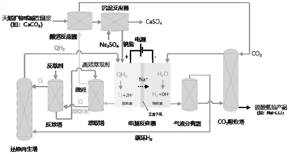
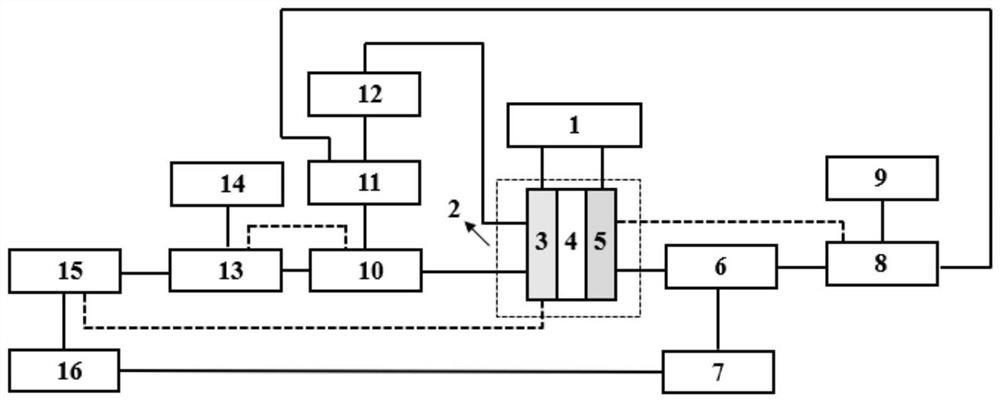
[0056] The system structure of this embodiment is as figure 2 As shown, the schematic diagram of the connection relationship of each device in the system is as described in the specific implementation, and the process is as in the attached figure 1 shown.

[0057] Using the structure in the specific embodiment to produce high-purity carbonate decoupling CO 2 Mineralized membrane electrolysis method, the specific operation is:

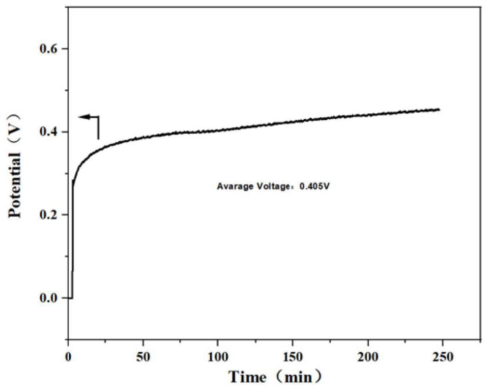
[0058] The cation exchange membrane Nafion 115 membrane is placed in the electrolytic cell, and the electrolytic cell is divided into a cathode area and an anode area, and 60ml of anolyte (0.01M substance ① tungstic acid derivative silicotungstic acid (SiW) + 0.5M Na 2 SO 4 ) and 60ml catholyte (1M NaHCO 3) is placed in a 200mL airtight storage tank, circulated through a pump at a flow rate of 20ml / min between the electrolyzer device, the storage tank, the extraction tower and the stripping tower, and passes into the reduction tower H 2 , the flow...

Embodiment 2

[0073] The operation process of this embodiment is basically the same as that of Example 1, the only difference is that 60ml of anolyte (leaching method to obtain red mud alkaline leaching solution+0.01M substance ② phenazine derivatives 2,3-dihydroxy-7- Phenazine sulfonate (DHPS)+0.25MNa 2 SO 4 ) and 60ml catholyte (0.5M NaHCO 3 ) is placed in a 200mL airtight storage tank, circulated through the pump between the electrolyzer device, the storage tank and the reduction tower at a flow rate of 20ml / min, and passes into the reduction tower H 2 The flow rate is 20ml / min, and the CO 2 Blow into the cathode area at a rate of 20ml / min. A DC power supply was applied between the anode electrode and the cathode electrode, and the electrolytic reaction was powered by an external DC power supply (IT6932A, Itech), and the temperature of the electrolytic cell and storage tank was set at 50 °C.

[0074] Set the current density to 10mA / cm 2 , the initial voltage is 0.181V, and the four-...

Embodiment 3

[0077] The operating process of this embodiment is basically the same as that of Example 1, the only difference being that 60ml of anolyte (the leaching method obtains red mud alkaline leaching solution+0.01M substance ③ alloxazine derivatives riboflavin (FMN)+0.5M Na 2 SO 4 ) and 60ml catholyte (1MNaHCO 3 ) is placed in a 200mL airtight storage tank, circulated through the pump between the electrolyzer device, the storage tank and the reduction tower at a flow rate of 20ml / min, and passes into the reduction tower H 2 The flow rate is 20ml / min, and the CO 2 Blow into the cathode area at a rate of 20ml / min. A DC power supply was applied between the anode electrode and the cathode electrode, and the electrolytic reaction was powered by an external DC power supply (IT6932A, Itech), and the temperature of the electrolytic cell and storage tank was set at 50 °C.

[0078] Set the current density to 10mA / cm 2 , the initial voltage is 0.15V, and the four-hour average voltage is 0...


PUM


Abstract

The invention belongs to the technical field of electrochemistry, and particularly relates to a decoupling type CO2 mineralization membrane electrolysis system for producing high-purity carbonate. According to the system, energy is supplied through an external power supply, the pH environment of a solution is changed through an electrochemical proton coupled electron transfer (PCET) reaction, high-concentration acid is extracted and purified through an efficient extraction separating agent so as to treat natural minerals or alkali liquor solid waste, and organic PCET reactants are reduced and regenerated through a non-electrochemical reaction, so that low-cost, high-efficiency and energy-saving effects are achieved. The invention relates to a stable operation process of a CO2 mineralization membrane electrolysis system with high resource conversion rate. According to the invention, the organic PCET reactant is adopted at the anode, so that the use of an H2 gas diffusion electrode is avoided; and CO2 is absorbed while hydrogen evolution reaction occurs on the cathode side, so that the influence of O2 and dissolved oxygen in CO2 on an anode organic PCET reactant is thoroughly avoided. And meanwhile, H2 generated by the cathode can be used as a reducing agent to realize reduction regeneration of an organic PCET reactant, so that continuous and stable operation of the CO2 mineralization membrane electrolysis system is realized.

Description

technical field [0001] The invention belongs to the technical field of electrochemistry, and specifically relates to a decoupled CO 2 Mineralized membrane electrolysis system. Background technique [0002] CO 2 Mineralization refers to the CO 2 The process of transforming into inorganic carbonate is CO 2 One of the key technologies for emission reduction utilization (CCU). At present, many domestic and foreign researches have carried out the use of bulk calcium and magnesium salt ores (serpentine, olivine, wollastonite) or solid waste (calcium carbide slag, steel slag, red mud) etc. 2 mineralization studies. [0003] However, the current CO 2 Mineralization utilization technologies generally face the technical problems of high energy consumption for mineralization reaction activation, high cost, and low economic value of products, which limit the CO 2 Feasibility of large-scale application of mineralization technology. However, using the proton cycle driven technolog...

Claims


Application Information

Patent Timeline
IPC IPC(8): C01D7/07C25B1/04C25B9/19C25B15/08C01B32/50C01F11/46
Inventor 刘涛吴一凡谢和平兰铖王云鹏赵治宇唐文彬
Owner SICHUAN UNIV
Why Eureka
Try Eureka