Method for reducing cracks of cladding coating on surface of stainless steel under high-temperature service

A high-temperature service, stainless steel technology, applied in the direction of coating, metal material coating process, etc., can solve the problems of reducing the service life of stainless steel, failure of stainless steel components, and accelerated corrosion of stainless steel parts

Pending Publication Date: 2022-04-29
ZHONGBEI UNIV
View PDF7 Cites 2 Cited by
  • Summary
  • Abstract
  • Description
  • Claims
  • Application Information

AI Technical Summary

Problems solved by technology

In a high temperature environment, some salts in a molten flow state or corrosive gases in the environment produced by power generation fuel will penetrate into the coating and even the stainless steel substrate through these cracks, causing oxidation and sulfidation in the coating, and accelerating the corrosion of stainless steel parts. Corrosion, so that the stainless steel components fail, greatly reducing the service life of stainless steel

Method used

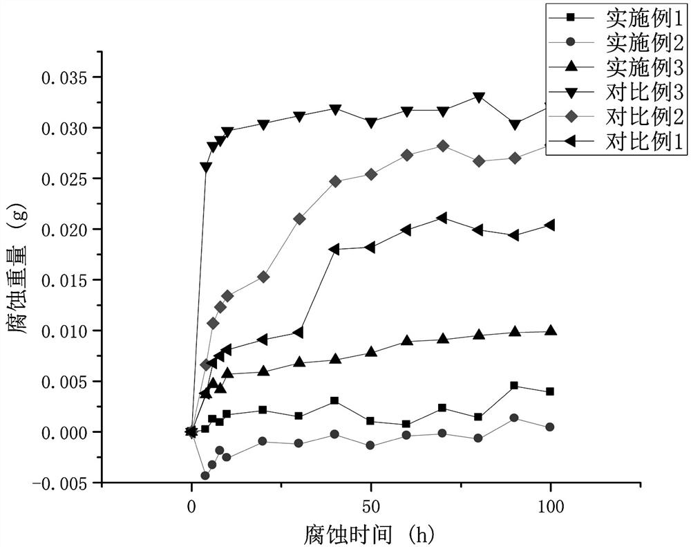
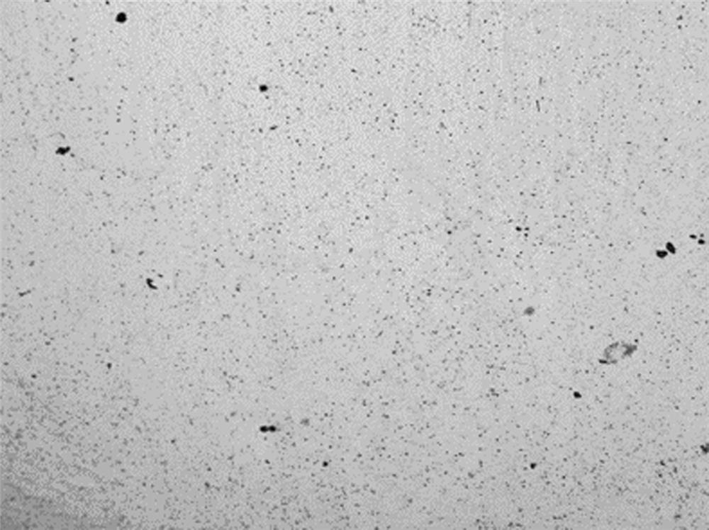
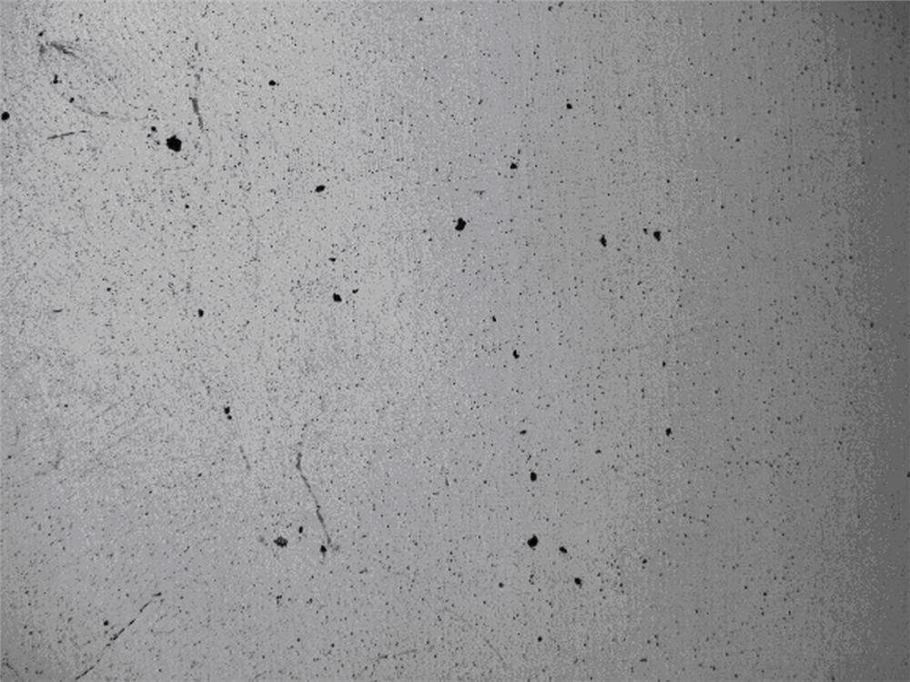

Image

  • Method for reducing cracks of cladding coating on surface of stainless steel under high-temperature service
  • Method for reducing cracks of cladding coating on surface of stainless steel under high-temperature service
  • Method for reducing cracks of cladding coating on surface of stainless steel under high-temperature service

Examples


Embodiment 1

[0036] Cut 17-4PH stainless steel into small pieces of 20×20×10mm to obtain stainless steel matrix.

[0037] After polishing the surface of stainless steel substrate with sandpaper of 150, 400, 800 and 1500 meshes in turn, clean it with absolute ethanol, then put it in an ultrasonic cleaner for cleaning, take it out and blow dry it to remove the residual oil, oxide and other impurities on the surface of stainless steel substrate.

[0038] The stainless steel substrate is placed in a muffle furnace, heated to 500℃ and preheated for 30min.

[0039] The laser cladding process parameters are set as follows: laser power 1800W, spot diameter 4mm, scanning speed 5mm / s, carrier pressure of alloy powder 0.8MPa, powder feeding rate 35mg / s, and scanning lap ratio 50%. Ni625 alloy powder with 150 meshes is loaded in the powder cavity of laser cladding device, and the preheated stainless steel substrate is placed on the laser cladding workbench. Under the action of powder feeder, the coaxial p...

Embodiment 2

[0045] The laser cladding process parameters are set as follows: laser power 1700W, spot diameter 4mm, scanning speed 8mm / s, carrier pressure of alloy powder 0.8MPa, powder feeding rate 35mg / s, scanning lap ratio 50%. Other operations are the same as in Example 1, and the protective layer is clad on the surface of stainless steel substrate.

[0046] After testing, the hardness of the stainless steel surface coating prepared above is 465HV. 0.1 .

Embodiment 3

[0048] The laser cladding process parameters are set as follows: laser power 1600W, spot diameter 4mm, scanning speed 7mm / s, carrier pressure of alloy powder 0.8MPa, powder feeding rate 35mg / s, scanning lap ratio 50%. Other operations are the same as in Example 1, and the protective layer is clad on the surface of stainless steel substrate.

[0049] After testing, the hardness of the stainless steel surface coating prepared above is 470HV. 0.1 .


PUM

PropertyMeasurementUnit
particle sizeaaaaaaaaaa
thicknessaaaaaaaaaa

Abstract

The invention discloses a method for reducing cracks of a cladding coating on the surface of stainless steel under high-temperature service, which comprises the following steps: performing laser cladding on Ni625 alloy powder on the surface of a preheated stainless steel matrix to form a transition coating, preheating again, performing laser cladding on NiCoCrAlY alloy powder to form a protective coating, cooling, heating to 150-250 DEG C in a vacuum environment, and performing vacuum low-temperature tempering treatment. By adding the transition coating and carrying out heat treatment on the formed cladding coating, on one hand, the internal stress of the coating can be released and relieved, and crack formation is inhibited; on the other hand, the cracking tendency of the coating can be solved by reducing the temperature gradient, and meanwhile, the hardness and the wear resistance of the coating can be improved, so that the high-temperature oxidation resistance and the corrosion resistance of the stainless steel are improved, and the service life of the stainless steel is prolonged.

Description

Technical field [0001] The invention belongs to the technical field of alloy surface modification, and relates to a method for reducing cracks of laser cladding coating on alloy surface at high temperature. technical background [0002] Coal-fired power generation still plays an irreplaceable role. But coal-fired power generation not only consumes a lot of energy, but also emits CO. 2 、SO 2 And other harmful gases. Therefore, in order to reduce energy consumption and environmental impact, it is necessary to improve the thermal efficiency of steam turbine power generation. [0003] Although it is a feasible way to improve the thermal efficiency of steam turbine units to reduce energy consumption and harmful gas emissions by increasing steam parameters, the continuous improvement of steam temperature and pressure has made the existing heat-resistant stainless steel more and more difficult to meet the actual demand. Therefore, it is necessary to continuously improve the performance ...

Claims


Application Information

Patent Timeline
Patent Type & Authority Applications(China)
IPC IPC(8): C23C24/10C21D1/773C23F17/00C22F1/10C22C19/05C22C30/00B22F9/04
CPCC23C24/106C21D1/773C23F17/00C22F1/10C22C19/058C22C30/00B22F9/04B22F2009/043
Inventor 李玉新田苗赵英虎白培康赵占勇魏守征
Owner ZHONGBEI UNIV
Why Eureka
Try Eureka