
Semi-solid material quick drying system

A semi-solid, material technology, used in drying solid materials, heating to dry solid materials, drying, etc., can solve the problems of unfavorable energy saving and emission reduction and large-scale promotion, high production and operating costs, uneven drying and other problems, and achieve Increase drying contact area, increase speed and efficiency, and increase drying efficiency

Pending Publication Date: 2022-06-07
EAST CHINA ENG SCI & TECH
View PDF0 Cites 1 Cited by
  • Summary
  • Abstract
  • Description
  • Claims
  • Application Information

AI Technical Summary

Problems solved by technology

At present, for the drying of semi-solid materials, due to the large heat transfer resistance, uneven drying, easy moisture return and low drying efficiency, it has become a technical difficulty in the drying process.
The traditional process drying system has high energy consumption, low thermal efficiency, high production and operating costs, and is not conducive to energy saving and emission reduction and large-scale promotion

Method used


Image

  • Semi-solid material quick drying system
  • Semi-solid material quick drying system
  • Semi-solid material quick drying system

Examples


Embodiment

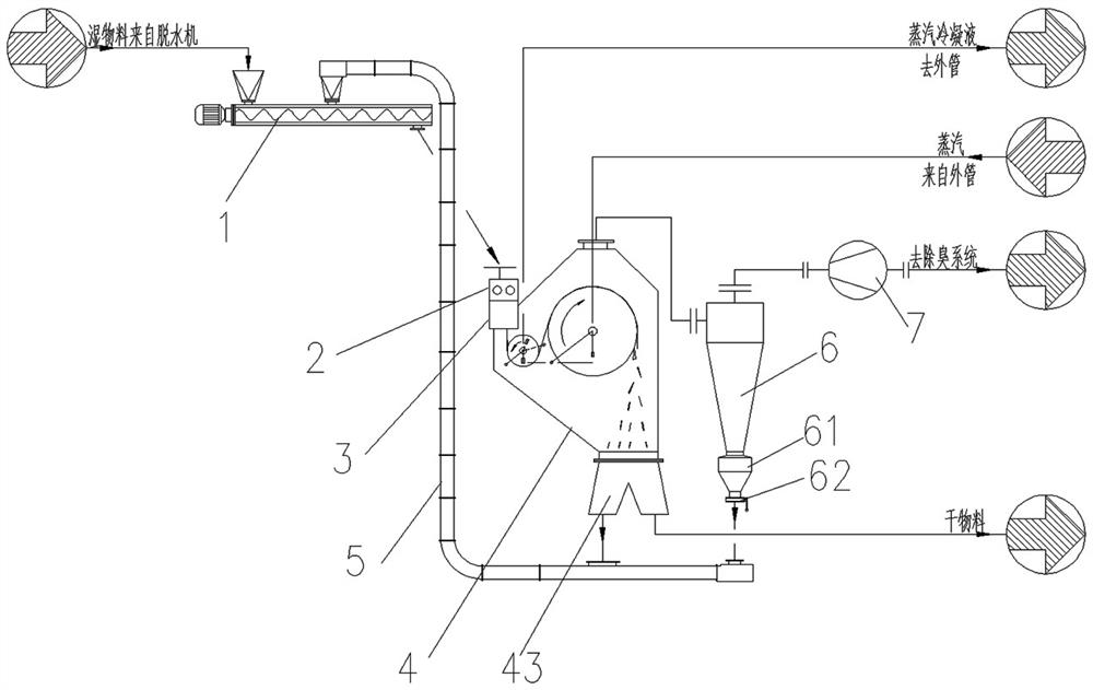
[0037] See figure 1 , a system for rapid drying of semi-solid materials,

[0038] Including shaftless double screw conveyor 1, distributor 2, forming machine 3, dryer 4, chain conveyor 5, cyclone separator 6 and exhaust gas fan 7, the distributor 2 and forming machine 3 are integrated models , the outlet of the cloth machine 2 is directly connected to the inlet of the molding machine 3;

[0039] A pair of stirring shafts 21 are arranged horizontally in the distributing machine 2, and stirring and mixing teeth 22 are evenly arranged on the outer cylindrical surface of each stirring shaft;

[0040] A pair of first rollers 31 , a pair of second rollers 32 and a pair of third rollers 33 are arranged horizontally from top to bottom in the forming machine 3 ;

[0041]Between the corresponding first roller and the stirring shaft, and between the corresponding first roller and the second roller through a chain transmission mechanism; the corresponding second roller and the third rol...

Embodiment 2

[0059] Take the drying treatment equipment in Example 1 as the treatment equipment of this embodiment; take the drying treatment of municipal sludge as an example; the moisture content of the wet sludge after the upstream dehydration is 70-80%, and the sludge treatment capacity is 2t / h ( Dry basis), the initial temperature of the sludge is 25°C at room temperature, the heating steam pressure of the dryer 4 is 0.6MPa, and the temperature is 150-165°C, which specifically includes the following steps:

[0060] Step (1): Start the exhaust fan 7, and the system pressure is stable after about 3 minutes;

[0061] Step (2): the drying roller 42 in the dryer 4 is fed with steam, the steam temperature is 150-165°C, and the heating temperature is adjustable, which can be determined according to the characteristics of the sludge and the final treatment requirements; after the steam is fed for 30s, the dryer 4. The inner drying roller 42 and the preheating roller 41 start to rotate, the ro...


PUM


Abstract

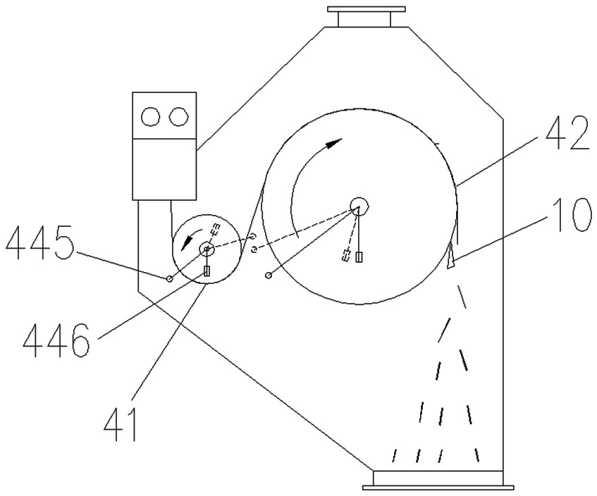
The invention belongs to the technical field of energy conservation and environmental protection, and particularly relates to a system for rapidly drying a semi-solid material. Comprising a shaftless double-screw conveyor, a material distributing machine, a forming machine, a drying machine, a chain conveyor, a cyclone separator and a waste gas fan, and the material distributing machine and the forming machine are of an integrated machine type; a preheating roller and a drying roller are arranged in the drying machine, and a separating knife is correspondingly arranged on the outer side wall of the corresponding drying roller above a lower outlet of the drying machine; a top air outlet of the drying machine is communicated with an inlet of the cyclone separator through a pipeline, a top air outlet of the cyclone separator is communicated with an air inlet of the waste gas fan through a pipeline, and semi-solid materials are conveyed to an inlet of the material distributing machine and mixed and stirred through the pair of stirring shafts to form particle materials. Particle materials are subjected to three-time extrusion forming through a pair of first rollers, a pair of second rollers and a pair of third rollers to form sheet-shaped materials, the sheet-shaped materials are preheated and dried at high temperature, dried particle materials are obtained through a separation knife, and the humidity of the dried particle materials is smaller than or equal to 30%.

Description

technical field [0001] The invention belongs to the technical field of energy saving and environmental protection, and in particular relates to a system for rapid drying of semi-solid materials. Background technique [0002] With the rapid development of modern industry and agriculture and the acceleration of urbanization, human beings are increasingly aware of energy conservation and environmental protection. Material drying has become an indispensable and important part of the industrial and agricultural process, especially the requirements for semi-solid materials are more prominent. At present, for the drying of semi-solid materials, due to the large heat transfer resistance, uneven drying, easy moisture return of materials, and low drying efficiency, it has become a technical difficulty in the drying process. The traditional process drying system has high energy consumption, low thermal efficiency, and high production and operation costs, which are not conducive to ene...

Claims


Application Information

Patent Timeline
IPC IPC(8): C02F11/00C02F11/13C02F11/121B01D45/16B01F29/64B01F35/30F26B3/24F26B13/08F26B13/18F26B25/22
CPCC02F11/00C02F11/13C02F11/121B01D45/16F26B13/08F26B13/183F26B3/24F26B25/22C02F2303/10F26B2200/18Y02P70/10
Inventor 张铭王争刚王晓波龚幸
Owner EAST CHINA ENG SCI & TECH
Learn More