Preparation method and application of metal current collector with micro-pit array
A technology of micro-pit array and current collector, which is applied in the direction of final product manufacturing, sustainable manufacturing/processing, electrode carrier/current collector, etc., can solve the problems such as the lack of research on the stress effect of mechanical means and the ambiguous design of micro-pit array parameters. Achieve large-scale production and application, simple and convenient processing methods, and good repeatability
- Summary
- Abstract
- Description
- Claims
- Application Information
AI Technical Summary
Problems solved by technology
Method used
Image
Examples
Embodiment 1
[0025] A preparation method and application of a metal current collector with a micropit array, comprising the following steps:
[0026] (1) Use a battery slicer to punch a copper current collector with a thickness of 50 μm into a disc with a diameter of 12 mm, and then use acetone and anhydrous ethanol to ultrasonically clean the copper foil to remove surface contamination;
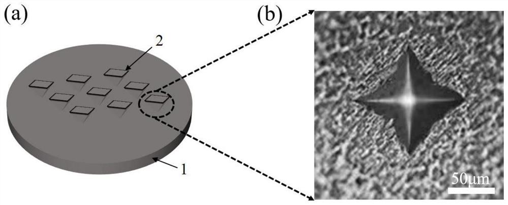
[0027] (2) Place the dried copper current collector substrate on the sample stage of the microhardness tester, and use a regular quadrangular pyramid indenter for mechanical indentation. The length of the bottom surface of the indenter is 140 μm and the height is about 20 μm; The load was 500 gf, and the array spacing was controlled to be 0.6 mm, and a copper current collector with a 10*10 micro-pit array pattern was pressed. A schematic diagram of a copper current collector with a micropit array pattern is shown in figure 1 As shown in (a), 1 is the copper current collector, 2 is the micro-pit on the c...
Embodiment 2
[0033] The basic steps are the same as in Example 1, the difference is:
[0034] In step (2), the press-in load is set to 300 gf, and a copper current collector with a micro-pit array pattern is pressed.
[0035] Taking the copper current collector with the micro-pit array pattern prepared above or the original copper current collector as the positive electrode, 1MLiTFSI+DOL / DME+2%LiNO 3 As the electrolyte, Celgard2400 with a diameter of 16 mm as the diaphragm, and a lithium sheet with a diameter of 12 mm as the negative electrode, a CR2032 button half-cell was assembled in an argon gas glove box, in which the volume ratio of DOL and DME was 1:1.
[0036] After standing for 12h, the Coulomb efficiency of the half-cell was tested by the Xinwei battery test system, and the current density was 1.0mA cm -2 , the charge-discharge depth is 1.0mAh cm -2 . like Image 6 As shown, compared with the pristine copper current collector, the copper current collector with the micropit ar...
Embodiment 3
[0038] The basic steps are the same as in Example 1, the difference is:
[0039] In step (2), the array spacing is controlled to be 1.0 mm, and a copper current collector with a micro-pit array pattern is pressed.
[0040] Taking the copper current collector with the micro-pit array pattern prepared above or the original copper current collector as the positive electrode, 1MLiTFSI+DOL / DME+2%LiNO 3 As the electrolyte, Celgard2400 with a diameter of 16 mm as the diaphragm, and a lithium sheet with a diameter of 12 mm as the negative electrode, a CR2032 button half-cell was assembled in an argon gas glove box, in which the volume ratio of DOL and DME was 1:1.
[0041] After standing for 12 hours, the Coulombic efficiency of the half-cell was tested by the Xinwei battery test system, and the current density was 2.0 mA cm -2 , the charge-discharge depth is 1.0mAh cm -2 . like Figure 7 As shown, at high current density, the copper current collector of the micropit array pattern...
PUM
| Property | Measurement | Unit |
|---|---|---|
| Depth | aaaaa | aaaaa |
| Diameter | aaaaa | aaaaa |
| Thickness | aaaaa | aaaaa |
Abstract
Description
Claims
Application Information
 - R&D
- Intellectual Property
- Life Sciences
- Materials
- Tech Scout
- Unparalleled Data Quality
- Higher Quality Content
- 60% Fewer Hallucinations
Browse by: Latest US Patents, China's latest patents, Technical Efficacy Thesaurus, Application Domain, Technology Topic, Popular Technical Reports.
© 2025 PatSnap. All rights reserved.Legal|Privacy policy|Modern Slavery Act Transparency Statement|Sitemap|About US| Contact US: help@patsnap.com


