
Biogas slurry decarbonization and deamination method and system

A biogas slurry and deamination technology, applied in the field of biogas slurry decarbonization and deamination methods and systems, can solve the problems of human health damage, pollution, waste of resources, etc., and achieve high ammonia nitrogen removal rate, high economic benefits, and strong operability. Effect

Pending Publication Date: 2022-08-09
锦益创典(天津)科技有限责任公司
View PDF0 Cites 0 Cited by
  • Summary
  • Abstract
  • Description
  • Claims
  • Application Information

AI Technical Summary

Problems solved by technology

The direct discharge of biogas slurry with high concentration of ammonia nitrogen will cause the following problems: eutrophication of water body, which will cause the deposition and transformation of pollutants, causing pollution to surface water and groundwater systems; soil eutrophication will cause algae to multiply, lead to a decrease in dissolved oxygen, and threaten The survival of aquatic organisms such as fish; the pollution of soil and water bodies will eventually affect human beings through the food chain, causing damage to human health; ammonia nitrogen is an important fertilizer resource and chemical raw material, and direct discharge causes resource waste and poor economic benefits
[0003] In related technologies, the focus of biogas slurry treatment is to remove suspended solids and organic matter in biogas slurry, and there are few studies on ammonia nitrogen removal methods, and the removal effect is poor
The more commonly used method is to flash the biogas slurry. The flash evaporation method is a primary treatment, and the ammonia nitrogen removal effect is poor. The treated biogas slurry will still contain high ammonia nitrogen, which is difficult to meet the discharge requirements.

Method used


Image

  • Biogas slurry decarbonization and deamination method and system
  • Biogas slurry decarbonization and deamination method and system
  • Biogas slurry decarbonization and deamination method and system

Examples


Embodiment 1

[0074]Input conditions:

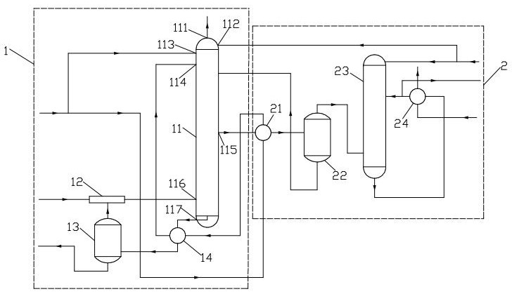
[0075] The total feed flow of biogas slurry to be treated is 25t / h, pH: 7.8-9.5; T: 30℃, P: 5.0bar; Composition: NH3-N: 4000-5000mg / L; COD: 5000-6000mg / L; SS: 2000mg / L; CO2: dissolved 5m3 / m3 biogas slurry to be treated.

[0076] The biogas slurry to be treated with a total feed flow of 25t / h is divided into two feeds, one of which passes through the second heat exchanger 21 and the first heat exchanger 14 after heat exchange, and then is input to the hot material inlet 114; the other Input to the cold feed inlet 113; and the flow rate of biogas slurry input to the hot feed inlet 114 accounts for 85% of the total feed flow, and the flow rate of biogas slurry input to the cold feed inlet 113 accounts for 15% of the total feed flow.

[0077] The primary steam is saturated steam: the feed flow rate is 2.5 t / h; P: 8.0 bar, which is input into the ejector 12 .

[0078] Fresh water fed to the spray inlet 112 of the stripper 11: feed flow 0.3 t / h, pH: 7, T:...


PUM


Abstract

The invention provides a biogas slurry decarbonization and deamination method and a biogas slurry decarbonization and deamination system. The method comprises the following steps: preheating to-be-treated biogas slurry and then feeding the biogas slurry to the upper part of a stripping tower; feeding stripping steam to the lower part of the stripping tower, carrying out countercurrent heat and mass transfer on the stripping steam and the preheated biogas slurry to be treated, and stripping carbon dioxide and ammonia gas in the preheated biogas slurry to be treated into a gas phase to obtain ammonia-carbon mixed steam; sending to-be-treated biogas slurry and / or a spraying agent to the upper part of the stripping tower, carrying out countercurrent heat and mass transfer on the to-be-treated biogas slurry and / or the spraying agent and the ammonia-carbon mixed steam, and removing ammonia gas from the ammonia-carbon mixed steam so as to enrich carbon dioxide at the top of the stripping tower and enrich ammonia gas in the middle of the stripping tower, the spraying agent comprises fresh water. According to the biogas slurry decarbonization and deamination method and system, efficient removal of ammonia carbon in the biogas slurry and recovery of carbon dioxide and ammonia gas can be achieved.

Description

technical field [0001] The invention relates to the technical field of biogas slurry treatment, in particular to a method and system for decarbonization and deamination of biogas slurry. Background technique [0002] After anaerobic fermentation of livestock manure, straw, kitchen waste, sludge, etc., biogas slurry containing high concentration of ammonia nitrogen will be produced. The direct discharge of biogas slurry with high concentration of ammonia nitrogen will cause the following problems: eutrophication of the water body, which will cause the deposition and transformation of pollutants, causing pollution to surface water and groundwater systems; rich and oxidized soil, causing algal blooms, leading to a decrease in dissolved oxygen, threatening The survival of aquatic organisms such as fish; the pollution of soil and water bodies will eventually act on human beings through the food chain, causing damage to human health; ammonia nitrogen is an important fertilizer res...

Claims


Application Information

Patent Timeline
IPC IPC(8): C02F1/02C02F1/04C02F1/10C02F1/20C01C1/02C02F101/10C02F101/16
CPCC02F1/02C02F1/10C02F1/20C02F1/043C02F1/041C01C1/022C02F2101/10C02F2101/16C02F2303/10Y02E50/30
Inventor 陈艳艳刘新哲盛晨军
Owner 锦益创典(天津)科技有限责任公司
Learn More