
Thermally powered oxygen/nitrogen plant incorporating an oxygen selective ion transport membrane

An ion transfer membrane, a technology for selecting ions, applied in the direction of oxygen/ozone/oxide/hydroxide, oxygen preparation, membrane, etc.

Inactive Publication Date: 2001-01-10
PRAXAIR TECH INC
View PDF15 Cites 13 Cited by
  • Summary
  • Abstract
  • Description
  • Claims
  • Application Information

AI Technical Summary

Problems solved by technology

The prior art indicates that ion transport membranes can be used to recover some of the oxygen that does not need to be combusted from the compressed air stream in the gas turbine cycle, however, this is accomplished at the expense of compressing additional feed air to replace the removed oxygen and Investment costs associated with oxygen removal systems

Method used


Image

  • Thermally powered oxygen/nitrogen plant incorporating an oxygen selective ion transport membrane
  • Thermally powered oxygen/nitrogen plant incorporating an oxygen selective ion transport membrane
  • Thermally powered oxygen/nitrogen plant incorporating an oxygen selective ion transport membrane

Examples


Embodiment 1

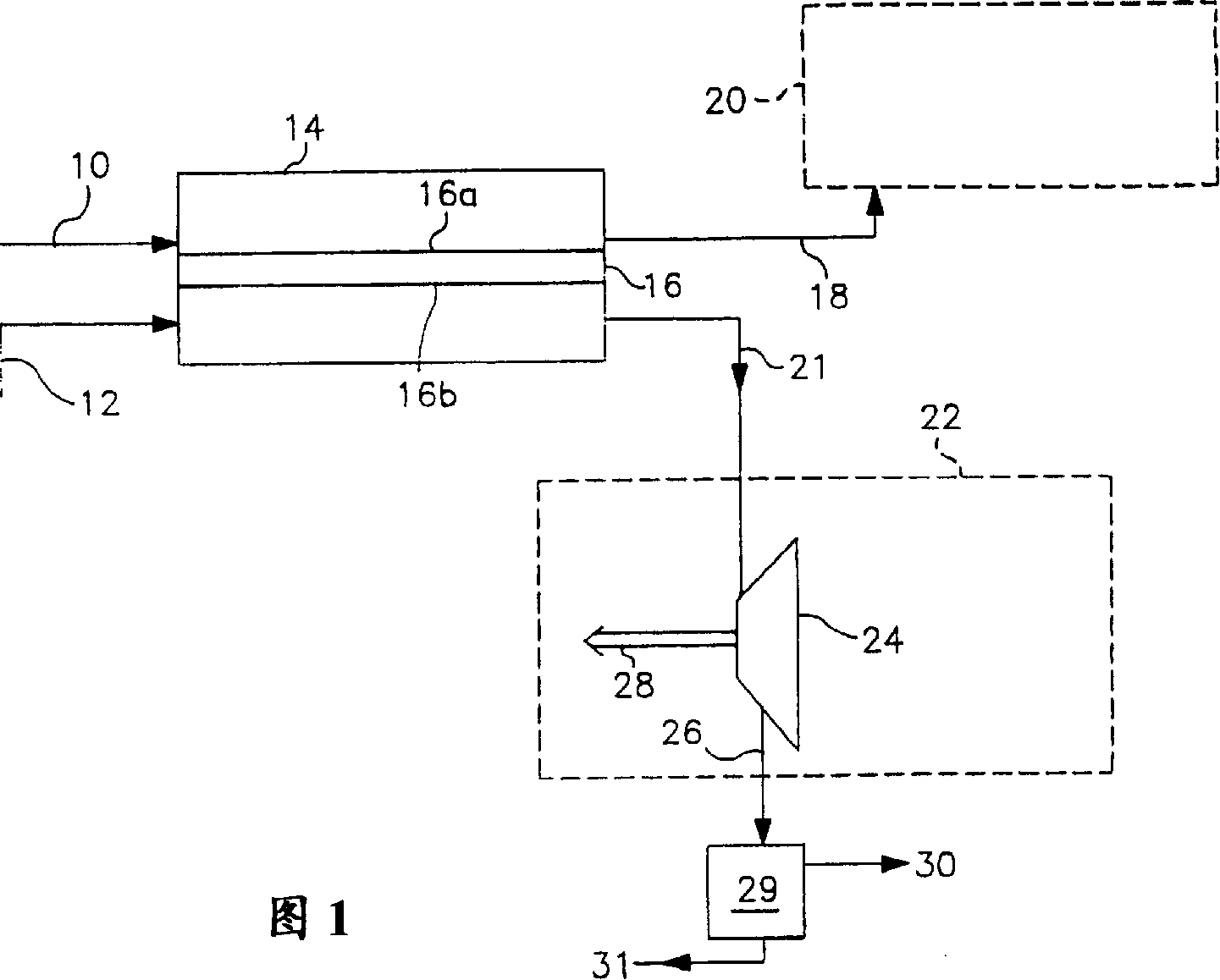
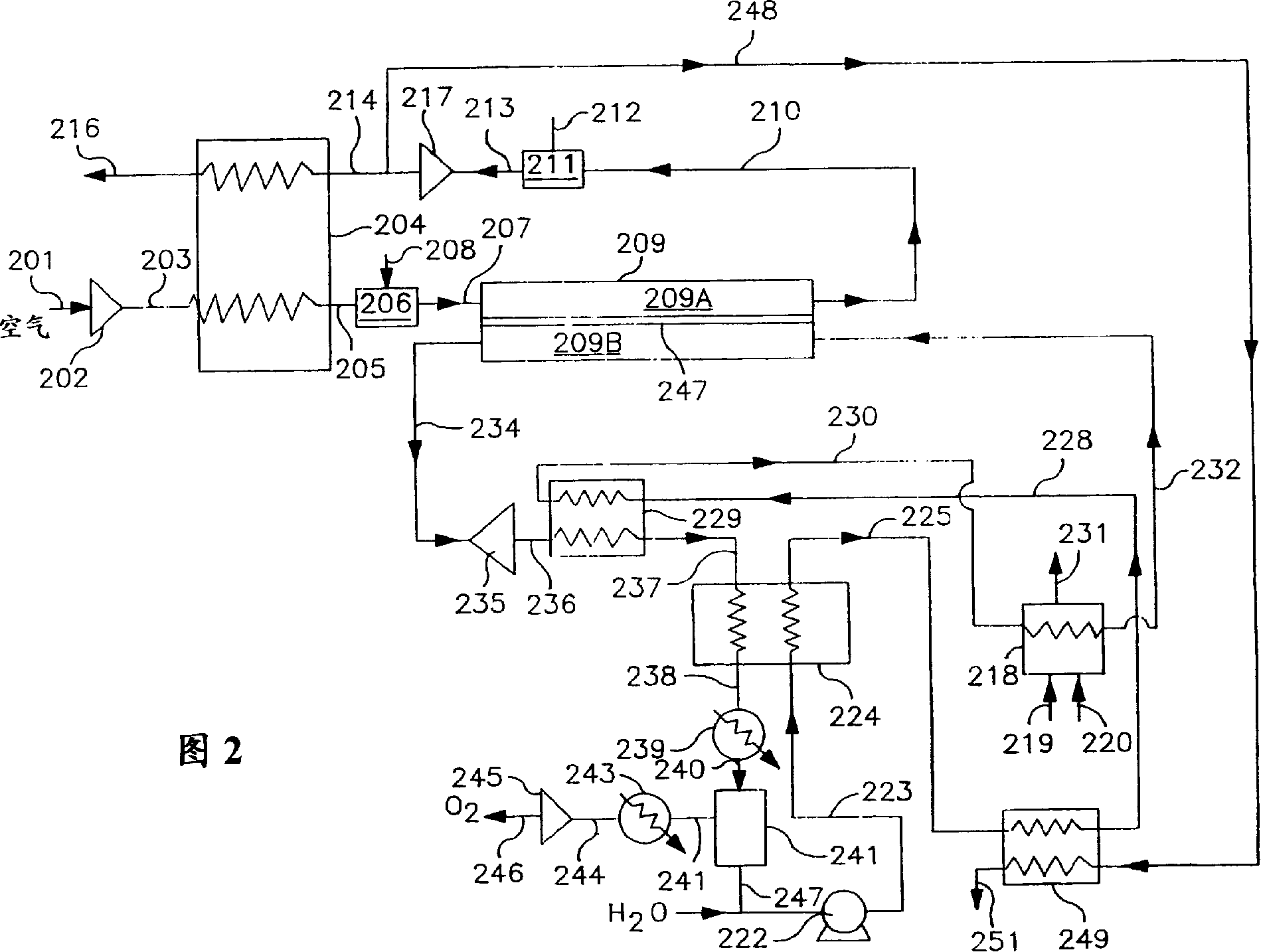
[0075] The following calculations were performed to compare the performance of three gas turbine cycles for simultaneous oxygen production: the system shown in Figure 2 of the present invention (case A); use of gas turbine exhaust to raise the temperature of the steam used to purge the permeate side of the ion transport generator, A cycle in which oxygen is delivered at elevated pressure (case B), and a gas turbine cycle with simultaneous oxygen production and no steam generation, where the turbine exhaust is used to regenerate preheated air (case C).

[0076] process conditions

[0077] Simultaneous production of oxygen: 1000 MNCFH

[0078] Air Compressor Discharge Pressure: 185 psia

[0079] Single-stage air compression AD. Eff=85%

[0080] Ion migration inlet temperature: 1650°F (900°C)

[0081] Turbine inlet pressure 180 psia

[0082] Turbine exhaust pressure 16 psia

[0083] Turbine Efficiency = 90%

[0084] Oxygen recovery rate: 5.6% of compressed air flow

[008...

Embodiment 2

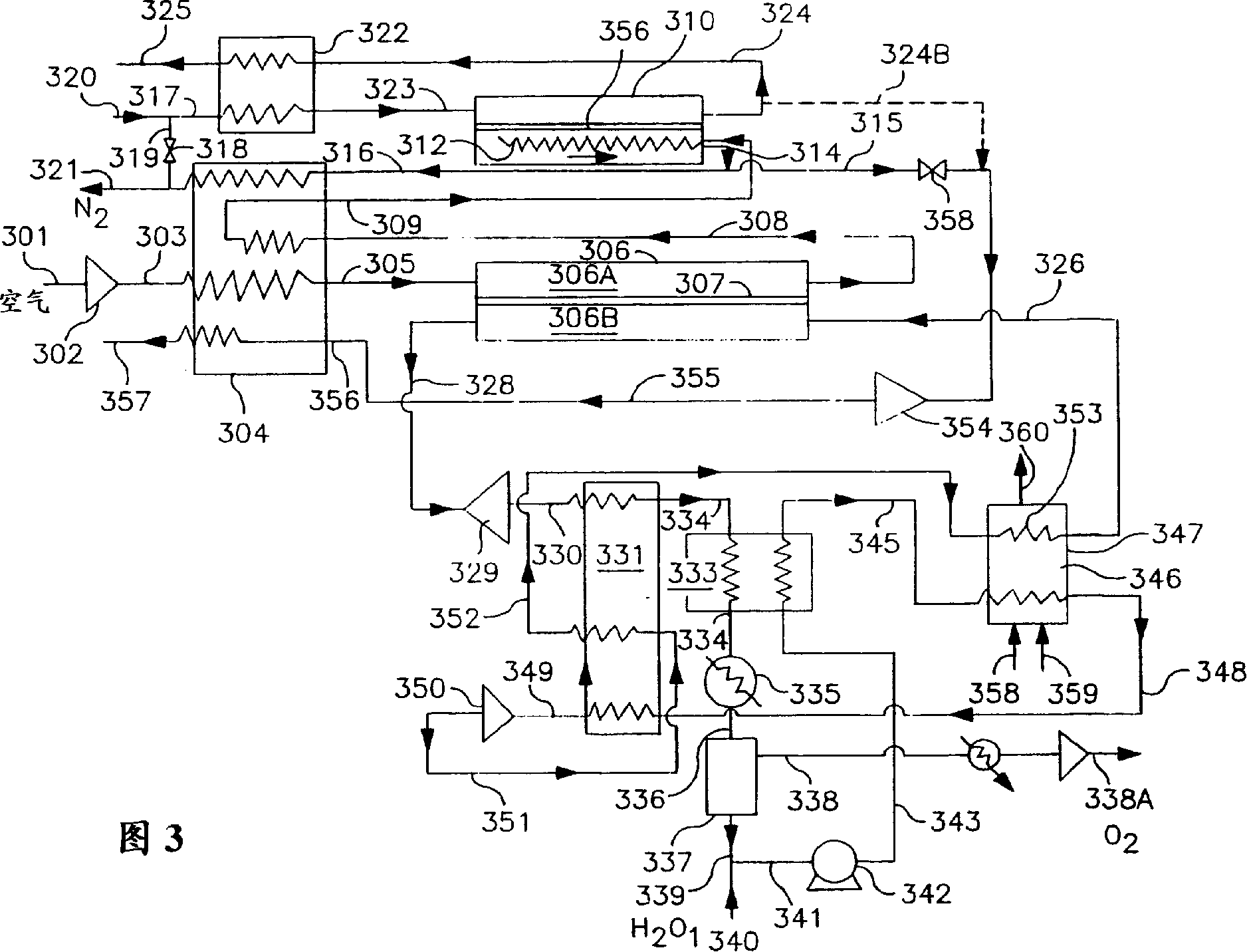
[0110] Example 2 Oxygen Product: 1000 MNCFH at 145 psia Nitrogen Co-Product: 1670 MM NCFH Air Compressor Discharge Pressure: 155 psia Air Compression Stages: 4 (compressor driven by thermal expander, not gas turbine) Air Compressor Efficiency = 85% Hot Gas Turbine Inlet Pressure: 150 psia Hot Gas Turbine Inlet Temperature: 1750°F (955°C) Hot Gas Turbine Exhaust Pressure: 16 pisa Hot Gas Turbine Efficiency: 90% Ion Mobility Separator Inlet Temperature: 1650°F (900°C) Ion Transport Deoxygen Outlet Temperature: 1750°F Deoxygenated Fuel Dilution 79 MNCFH N 2 High pressure turbine inlet pressure: 1000 pisa High temperature turbine inlet temperature: 805°F (430°C) Low pressure turbine inlet pressure: 150 pisa Low pressure turbine inlet temperature: 1650°F Low pressure turbine exhaust gas pressure: 16 psia Turbine efficiency: 90% Steam condensing pressure: 14.7 Steam produced by pisa: 303 M lbs / Hr Result: Oxygen recovery: % of O in the feed air 2 83% of N under 145 pisa 2 Co-produc...

Embodiment 3

[0159] The following embodiment is to apply the process shown in Figure 4 and Figure 5 The reactor design shown is obtained assuming the following conditions:

[0160] Air Flow: 1130 MNCFH.

[0161] The air is compressed to 115 psia in 3 stages, which has a thermal insulation efficiency of 85%.

[0162] Flow into Reactor Separator Cooler:

[0163] 225 MNCFH at 120°F

[0164] 905 MNCFH, 400°F

[0165] Maximum Oxygen Transport Membrane (OTM) Operating Temperature: 1760°F

[0166] Average OTM separator driving force: log(PO 阴极 / PO 阳极 )=0.3

[0167] Nitrogen exits separator reactor cooler at 1300°F

[0168] Turbine Flow: 680 NCFH of N at 1300°F 2 .

[0169] Turbine Efficiency: 68%

[0170] Purge steam: 4.21 1bs / hr.

[0171] Fuel: 900 BTU / NCFH low calorific value natural gas

[0172] Fuel Consumption: 18900 NCFH

[0173] Product flow:

[0174] 200 MNCFH of oxygen (91.4% O 2 , 8.6% CO 2 ), 15 psia.

[0175] The nitrogen of 212 MNCFH (O 2 <10 ppm), 100 psia

[...


PUM

PropertyMeasurementUnit
thicknessaaaaaaaaaa

Abstract

A low energy cost process for the co-production of oxygen and nitrogen product gases employs a fuel feed tube (506) which extends into oxygen selective ion transport membrane (424) whereby fuel (440) is introduced adjacent its closed end and flows concurrently with oxygen containing gas in annulus (510) and an oxygen selective ion transport membrane having separator section (436) and reactor section (438). Oxygen-containing feedstock (406) is compressed and then contacts cathode side (426) of separator section (436) where a portion of the oxygen is transported to anode side (428) and recovered as an oxygen product gas. Substantially the remainder of the oxygen is transported from cathode side (426) to anode side (428) and exothermically reacted with a fuel. Hot nitrogen rich product gas is expanded into a turbine to generate the power necessary to compress the feedstock.

Description

[0001] Cross-references to related patents [0002] This application is US Patent Application No. Part of the subsequent application of 08 / 972,020 (Attorney's Docket No. D-20,345), its title is "Solid Electrolyte Ionic Conductor Oxygen Production with Power Generation", its inventors are Keskar et al., and its filing date is November 1997 18, the entire application document is hereby incorporated by reference. field of invention [0003] The present invention relates to the use of solid electrolyte ion conductor systems in gas separation systems, and in particular, to the use of combustion products and / or steam from a combined ion transport membrane reactor to purge the permeate side of a solid electrolyte ion conductor membrane to enhance the efficiency of the process , and produces a stream of oxygen, carbon dioxide, and steam that is easily separated for pure oxygen, while producing nitrogen at elevated pressure and generating enough energy to drive the system air compress...

Claims


Application Information

Patent Timeline
Patent Type & Authority Applications(China)
IPC IPC(8): B01D53/04B01D53/047B01D53/22C01B13/02C01B21/04
CPCB01D2313/22B01D2313/40B01D63/06B01D2257/702B01D2256/12B01D2259/40001B01D2259/40079B01D2259/40081B01D53/22C01B21/0438C01B2210/0062B01D53/0462B01D2257/80B01D2259/40052Y02C10/10Y02C10/08B01D2257/504C01B13/0251B01D2256/10C01B2210/0046B01D53/047B01D53/229Y02P20/129Y02C20/40Y02P20/151B01D2313/221
Inventor C·F·戈蒂曼恩R·普拉萨德N·R·科斯卡J·B·伍尔夫
Owner PRAXAIR TECH INC
Learn More