Intelligent type valve electrical device

An electric and intelligent technology for valves, applied in the direction of valve devices, valve operation/release devices, valve details, etc., can solve problems such as zero drift, intermittent analog signals, precision distortion, etc., to protect the pipe network system and solve complex structures , the effect of high repeatability

Inactive Publication Date: 2005-01-26
郭振兴
View PDF0 Cites 22 Cited by
  • Summary
  • Abstract
  • Description
  • Claims
  • Application Information

AI Technical Summary

Problems solved by technology

[0003] 1. The structure is complex: the main reducer part is a mechanical structure, while the control part is an electromechanical structure, such as the torque control mechanism DSW and the valve opening control mechanism
[0004] 2. Low accuracy of output shaft torque detection and valve opening detection: the detection value is transmitted through gears, amplified by a counter, and then output through potentiometers, cams and contacts. After such a complicated electromechanical process, its accuracy There will be a lot of distortion, especially the detection value of the torque, which is output after being amplified by the deformation of the spring under the action of an external force, and the torque accuracy is only ±7~10%, which cannot be further improved
In addition, due to the limitation of the number of mechanical contacts on the cam, the output detection value can only be a discontinuous analog signal
However, intermittent analog signals cannot meet the requirements of networking
[0005] 3. Poor use safety: the output of the cam and contact works under the condition of strong electricity, it is very easy to cause poor contact or ignition, and there are great hidden dangers
[0006] 4. Low working reliability: The counter of the existing valve electric device is an instrument gear structure. The contact signal value is determined by manually adjusting the screw (positioning) with a screwdriver. Often, the gear meshing is not in place and the positioning is inaccurate, resulting in failure. Or accidents often occur, seriously affecting the reliability of electric valve work
[0007] 5. The closing zero point will drift: the existing valve electric device, the initial closing position (zero point) will change with the deformation and wear of the valve sealing surface and the torque when the valve is closed during the use of the electric valve. change
The problem of zero point drift at the closing point is difficult to solve for electromechanically controlled electric valves, which will have serious consequences for the sealing performance of electric valves in long-term use
[0008] 6. A single opening and closing speed is likely to cause water hammer phenomenon: because the existing valve electric device has a single speed in the working process, it is easy to cause "water hammer" phenomenon when the valve with a larger diameter in the pipe network system is closed. , so that there will be a dangerous accident of pipe explosion in the pipe network system

Method used


Image

  • Intelligent type valve electrical device
  • Intelligent type valve electrical device
  • Intelligent type valve electrical device

Examples


Embodiment 1

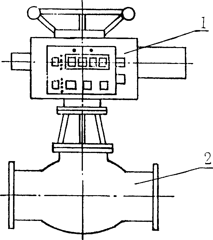
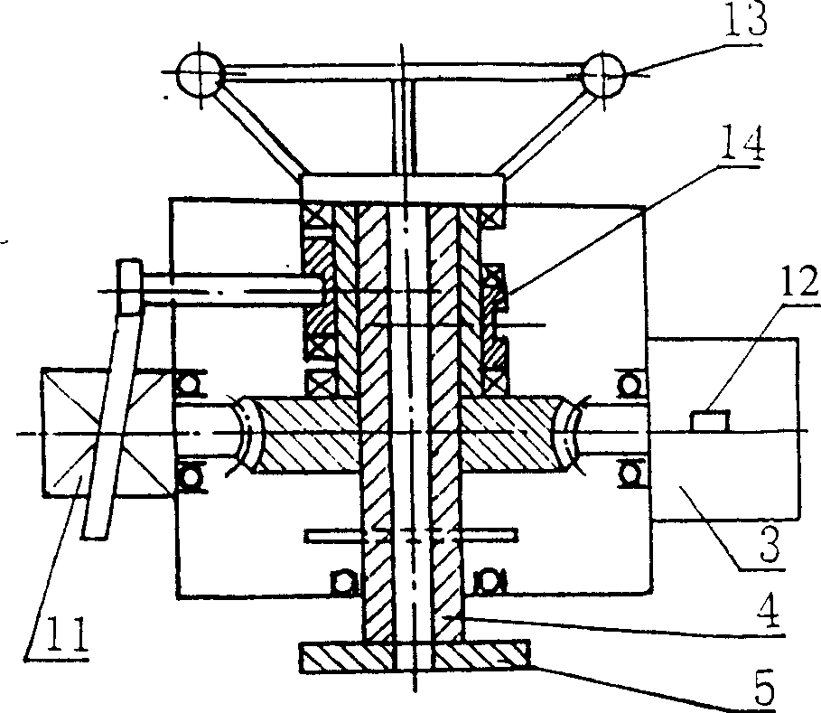
[0048] The multi-turn valve electric device is composed of a mechanical structure part and an electric control part. The mechanical part maintains the existing structure, that is, it is still equipped with a motor, a reduction mechanism, and a drive mechanism. The reduction mechanism includes a gear pair and a worm pair, and the drive mechanism includes a worm gear. 7 and its output shaft 4, the flange connection plate 5 and the hand wheel mechanism 13 connected to one end of the output shaft, and the manual-electric switching device 14 located between the hand wheel and the output shaft.

[0049] The feature of the present invention is that the mechanical structure part is only used as the carrier for the mechanical motion transmission of the valve electric device, and does not participate in the detection and control of the valve. It is set independently from the electric control part 9 . The original electromechanical torque control mechanism and valve opening control mechan...

Embodiment 2

[0066] Part-rotary valve electric device, the output shaft torque value detector in this device adopts a magnetic coupler, and other structures are the same as in Embodiment 1.

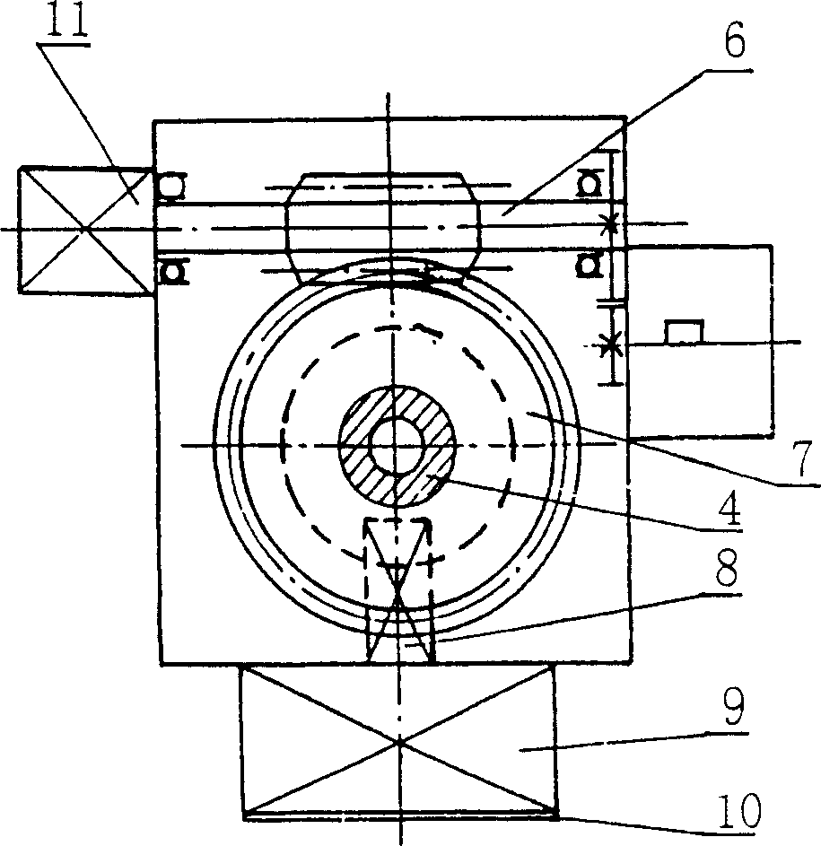
[0067] see below Figure 8 , the magnetic coupling is installed between the worm shaft 6 and the motor 3, and the magnetic coupling is composed of an armature 43 coaxially sleeved on the motor shaft 38 and a permanent magnet 40 fixed in the worm shaft end sleeve 39, The armature is cup-shaped, the permanent magnet is cylindrical, and the permanent magnet 40 is sleeved outside the armature 43. The two are coaxial, and there is a sliding fit between the armature and the permanent magnet. There is a compression collar 41 on the top of the permanent magnet.

[0068] The working process of the magnetic coupler is that when the motor 3 rotates, the motor shaft 38 drives the armature 43 to rotate, and the permanent magnet 40 and the worm shaft 6 rotate together within the set torque value, and drive the code...


PUM


Abstract

The intelligence valve electrically controlled installment belongs uses the sensor monitor and the micro electron technology control valves uses the electrically operated installment. The main characteristic is: In the mechanism which has has partially established the non- electronic contact type examination output shaft torque value the strength value sensor and the examination valve operates the electro-optical sensor, in the electric motor supposes the temperature sensor; Its electric control are partial is the modular microcomputer control system, in is equipped with AVR high speed to insert the type monolithic integrated circuit the controller module, receives various sensors the monitor signal to control the power control module after processing, then control motor active status. This invention solved the traditional technology to plant the structure complex, security bad, difficult problem and so on reliability, this equipment was the light integration of machinery high tech product, its structure simple, security good, precision high, the reliability was high, could to the valve entire work process realization automatic monitor and the monitoring.

Description

technical field [0001] The invention relates to an electric device for a valve using sensor detection and microelectronic technology control. The device is matched with the valve to form an electric valve to implement automatic control and management of the medium parameters conveyed in the pipe network system. Background technique [0002] The current national professional standard for valve electric devices JB / T8528-1997 stipulates that it is applicable to ordinary type valves such as motor drive, electric contact control, single speed gate valve, globe valve, throttle valve, diaphragm valve, ball valve and butterfly valve. electric device". This type of electric device is based on the reduction mechanism driven by the motor. The main body is equipped with springs, mechanical gears, counters, cams, potentiometers, contacts and other mechanisms to detect and control the valve opening and valve torque. , The operation of the valve is completed by electromechanical control. ...

Claims


Application Information

Patent Timeline
Patent Type & Authority Applications(China)
IPC IPC(8): F16K31/05F16K37/00
Inventor 郭振兴蒋照虎邸晓华
Owner 郭振兴
Why Eureka
Try Eureka