

Metallic structures incorporating bioactive materials and methods for creating the same
A bioactive, metal alloy technology, applied in the types of packaging items, special packaging items, packaging, etc., can solve problems such as stability limitations of bioactive materials
- Summary
- Abstract
- Description
- Claims
- Application Information
AI Technical Summary
Problems solved by technology
Method used
Image

Examples
preparation example Construction
[0099] A. Preparation of matrix
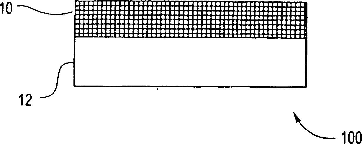
[0100] Any suitable substrate may be coated with embodiments of the present invention. The substrate may be porous or solid, and may have a flat or uneven surface (eg, a curved surface). The substrate can also be flexible or rigid. In certain embodiments, the substrate may be a stent body, implant, particle, pellet, electrode, and the like.
[0101] The matrix may comprise any suitable material. For example, the substrate may comprise metal, ceramic, polymeric material, or composite material. For example, the substrate may include metals such as stainless steel or Nitinol (Ni-Ti alloy). Alternatively, the matrix may comprise polymeric materials, including fluoropolymers such as polytetrafluoroethylene. In some embodiments, the substrate can include a sacrificial material. A sacrificial material is a material that can be removed, eg, by etching, leaving a free-standing bioactive composite structure.
[0102] Any suitable method may be us...
Embodiment 1
[0159] Six bioactive composite structures were prepared. Each bioactive composite structure includes a nickel-phosphorus metal matrix formed on a metal substrate by electroless deposition. The substrate used is a metal foil. 3 substrates include medical grade 316L stainless steel and 3 substrates include Nitinol. Fluorouracil, tetracycline, and albumin were co-deposited with nickel-phosphorus on stainless steel and nitinol substrates, respectively.
[0160] Each substrate was first prepared using the process steps shown in Figure 4. First the surface of the substrate is cleaned (step 32). The surface of the substrate is then rinsed with distilled water (step 34). After rinsing, the surface of the substrate is sensitized with Sn(II) (step 36). A 0.1g / L stannous chloride solution can be used as a sensitizing solution. After depositing Sn(II) on the surface of the substrate, the substrate is rinsed again with distilled water (step 38 ) in a second rinsing step. Then, a Pd(...
Embodiment 2
[0167] The same baseline electroless deposition method as in Example 1 was used to prepare coated stents. However, in this example, the Johnson Bx Velocity Stent (stainless steel) and the Johnson Smart Stent (Nitinol) were used as the substrate instead of the metal foil substrate. Bioactive composite structures in the form of layers are produced on scaffolds.
[0168] Image 6 Shown is the drug elution gradient curve when Johnson & Johnson Bx Velocity Stent (316 stainless steel) is used as the substrate. Figure 7 Shown is the drug elution gradient curve when Johnson & Johnson Smart stent (Nitinol) is used as the matrix. The amount on the y-axis of the curve represents the amount of bioactive material that remained on the scaffold after elution into saline solution.
[0169] The anodization process employed in the stent embodiment is similar to that applied again to the metal foil substrate. After coating, the coated stents were placed in physiological saline solution and ...
PUM
| Property | Measurement | Unit |
|---|---|---|
| Thickness | aaaaa | aaaaa |
| Thickness | aaaaa | aaaaa |
| Thickness | aaaaa | aaaaa |
Abstract
Description
Claims
Application Information