Integrated assembly and substrate structure and its production for polymer ultraviolet/visible-light collimator

A visible light and polymer technology, applied in the direction of microstructure technology, microstructure devices, manufacturing microstructure devices, etc., can solve the problems of high production cost, long production cycle and complicated process of silicon wafer V-shaped groove structure for positioning, and achieve High signal-to-noise ratio, satisfying multi-index inspection, and improving coupling efficiency

Inactive Publication Date: 2007-01-17
CHANGCHUN INST OF OPTICS FINE MECHANICS & PHYSICS CHINESE ACAD OF SCI
View PDF0 Cites 3 Cited by
  • Summary
  • Abstract
  • Description
  • Claims
  • Application Information

AI Technical Summary

Problems solved by technology

[0007] In order to solve the first problem in the background technology, a common near-infrared fiber optic self-focusing lens is used to form a collimator assembly, which only has the best coupling efficiency for a single wavelength of light. When used in the multi-wavelength range of 220nm to 800nm, it will The parallelism of the cup light becomes worse, and the coupling efficiency of light decreases, which greatly affects the accuracy of sample biochemical analysis; second, the V-shaped groove structure of the silicon wafer for positioning has a long production cycle, complex process, high production cost, and is relatively brittle and fragile , which brings great inconvenience to assembly and use, and reduces the reliability of device use. The present invention proposes an optical collimator integrated assembly structure and manufacturing method suitable for wide-spectrum detection in micro-biological and chemical testing technology. The purpose of the invention is to improve the parallelism and optical coupling efficiency of light in the wavelength range of 220nm to 800nm ​​in the miniature biochemical inspection optical detection system, simplify the manufacturing process of the optical collimator component, reduce the manufacturing cost, and improve the detection accuracy and reliability

Method used


Image

  • Integrated assembly and substrate structure and its production for polymer ultraviolet/visible-light collimator
  • Integrated assembly and substrate structure and its production for polymer ultraviolet/visible-light collimator
  • Integrated assembly and substrate structure and its production for polymer ultraviolet/visible-light collimator

Examples


Embodiment 1

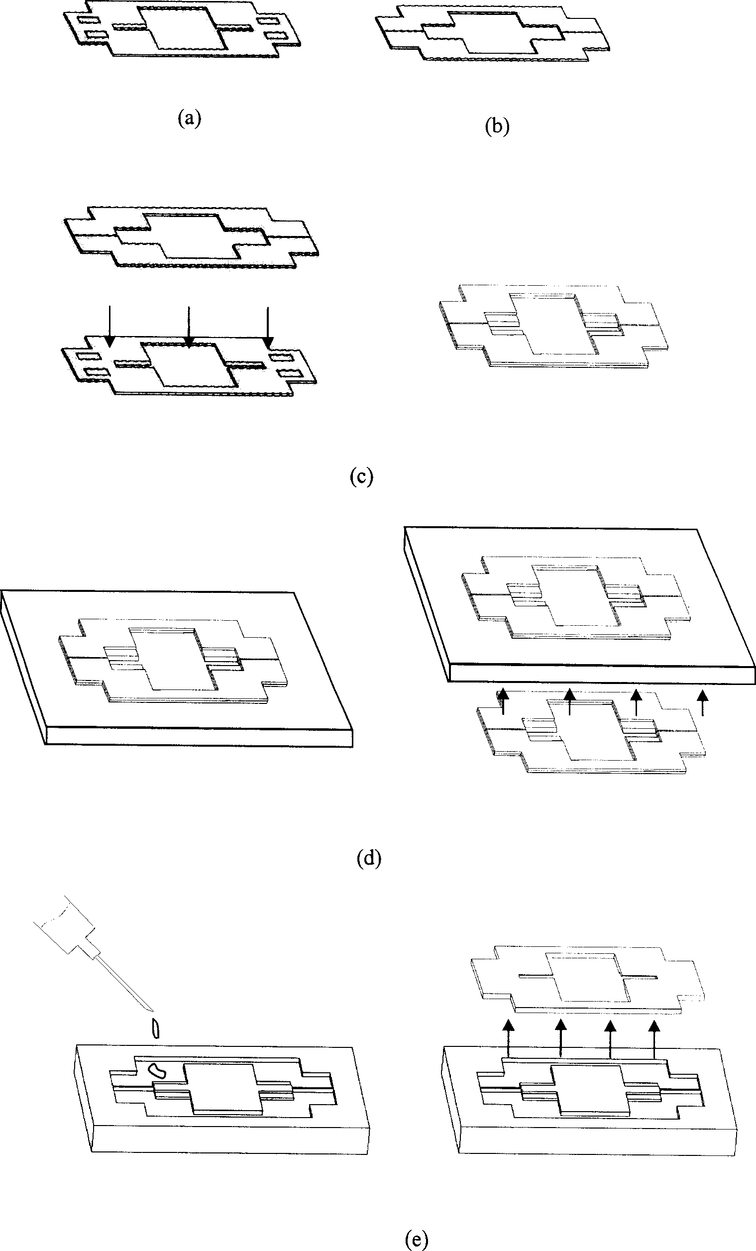
[0019] The fabrication method of the polymer ultraviolet / visible light collimator integrated component substrate structure proposed by the present invention is as follows: image 3 shown.

[0020] (1) Using photolithography, wet etching and other processes in micromechanical silicon processing technology, select a 380 μm thick double-sided polished and oxidized Si single wafer, and make a first V-shaped groove with a width of 2.16 mm on the front side of the Si single wafer 4 and the second V-shaped groove 6; and then use photolithography, dry etching and other processes to make four rectangular positioning holes 12 with a side length of 2 mm × 3 mm on the front side of the Si single wafer, and the depth of the positioning holes 12 is 0.1 mm. The first sample cup groove 13 is transparent and located at the center of the Si single wafer, and the first sample cup groove 13 adopts a rectangular structure. Make the first substrate 1 that contains the first V-shaped groove 4, the ...

Embodiment 2

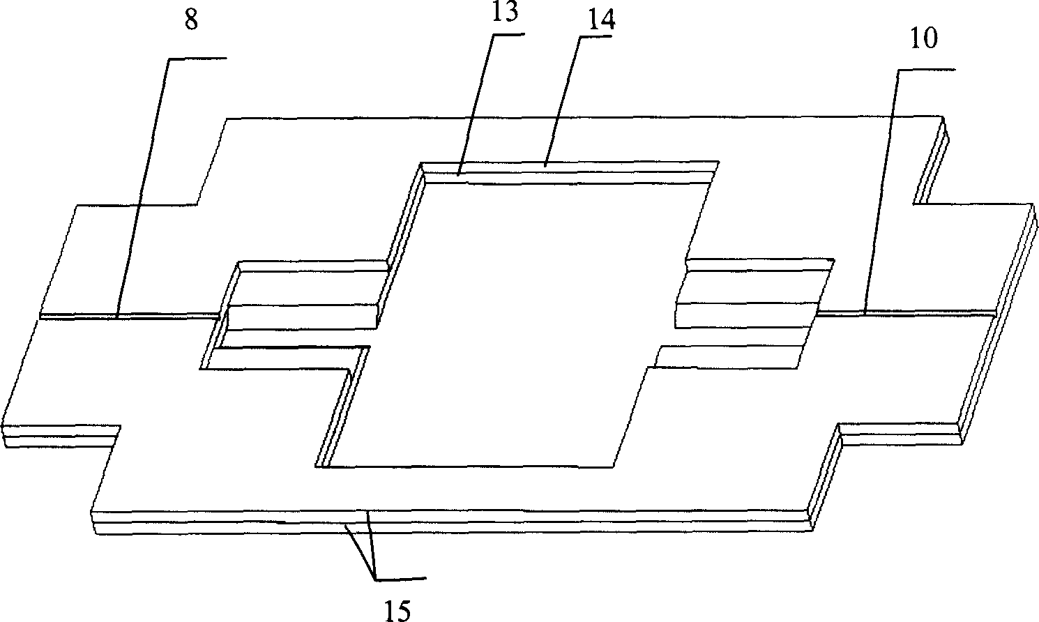
[0026] The manufacturing method of the polymer ultraviolet / visible light collimator integrated assembly structure proposed by the present invention can be utilized to manufacture the substrate structure mold, such as figure 2Shown: by the first substrate 1 and the second substrate 2, the first V-shaped groove 4, the second V-shaped groove 6, the third V-shaped groove 8, the fourth V-shaped groove 10, a plurality of positioning pins 11, A plurality of positioning holes 12, a first sample cup groove 13 and a second sample cup groove 14 are formed. On the body of the first substrate 1, a first V-shaped groove 4, a second V-shaped groove 6, a plurality of The positioning hole 12 and the first sample cup groove 13 are respectively prepared with a third V-shaped groove 8, a fourth V-shaped groove 10, a plurality of positioning pins 11 and a second sample cup groove 14 on the body of the second substrate 2 , a plurality of positioning pins 11 are placed in a plurality of positioning...

Embodiment 3

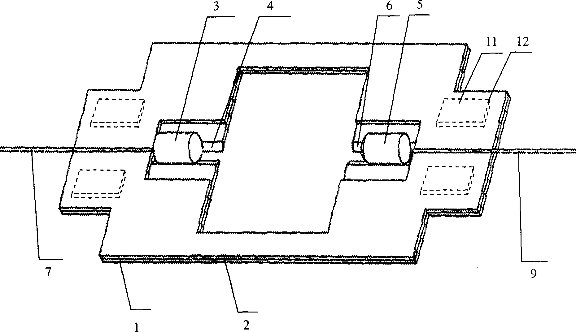
[0029] The method for making an integrated component structure of a polymer ultraviolet / visible light collimator proposed by the present invention can be used to manufacture component structures, such as figure 1 Shown: the input lens 3, the first V-shaped groove 4, the output lens 5, the second V-shaped groove 6, the input optical fiber 7, the third V-shaped groove 8, the output optical fiber 9, the fourth V-shaped groove 10, the first The sample cup groove 13, the second sample cup groove 14 and the substrate 15 are composed of the input lens 3, the first V-shaped groove 4, the output lens 5, the second V-shaped groove 6, the input optical fiber 7, the first V-shaped groove on the substrate 15 body. Three V-shaped grooves 8, output optical fiber 9, fourth V-shaped groove 10, first sample cup groove 13 and second sample cup groove 14, input lens 3 is placed in the first V-shaped groove 4, output lens 5 is placed in In the second V-shaped groove 6, the input optical fiber 7 is...


PUM


Abstract

The invention relates to the polymer ultraviolet or visible light collimator integration component, the chip mould and the production method. On the first and the second substrate set the first, the second, the third, the fourth V-shape slot, the fixed hole, the fixed cross-pin, the first and the second sample cup slot. The fixed cross-pin inserts the fixed hole to form the female die. On the negative die produces the male die and injection mould into the same polymer chip structure with the female mould. The component and the mould is composed of the first and the second substrate or chip, the input and the output lens, the first, the second, the third and the fourth V-shape slot, the input and the output optical fiber, the fixed cross-pin and hole, the first and the second sample cup slot. It solves the problem that biochemical checking wavelength span is limited. The light coupling efficiency and the checking veracity is increased between 220 and 800nm. The polymer double layer V-shape slot realizes the precise localization of the optical fiber and the lens. It decreases the production cycle and the cost and increases the consistence and the reliability.

Description

technical field [0001] The invention belongs to the field of Micro-Opto-Electro-Mechanical Systems (MOEMS), and relates to an integrated component of an ultraviolet / visible light collimator used in a miniature biochemical analyzer. Background technique [0002] Biochemical testing is aimed at the research of biochemical processes in health and disease. By measuring the components of tissues and body fluids, it reveals the effects of disease and drug treatment on the biochemical processes of the body and the components of tissues and body fluids, so as to provide disease diagnosis and condition monitoring. , drug efficacy, prognosis and useful information for disease prevention. [0003] In recent years, testing instruments have mainly developed in two directions. One is a complete analytical laboratory with fully automatic or semi-automatic multiple analysis functions, and the other is "Point of Care Testing" (POC) technology. POC is a revolutionary technology. The introduc...

Claims


Application Information

Patent Timeline
Patent Type & Authority Applications(China)
IPC IPC(8): G02B6/26G02B6/32G01N21/00B81C1/00
Inventor 张平吴一辉周连群李淑娴刘永顺王淑荣
Owner CHANGCHUN INST OF OPTICS FINE MECHANICS & PHYSICS CHINESE ACAD OF SCI
Why Eureka
Try Eureka