Lead storage battery

A technology of lead storage battery and negative electrode, which is applied in the field of improvement of service life characteristics, can solve the problems of corrosion of the negative electrode grid and the corrosion of the connection piece, and achieve the effect of inhibiting corrosion

Active Publication Date: 2007-03-28
GS YUASA INT LTD
View PDF0 Cites 14 Cited by
  • Summary
  • Abstract
  • Description
  • Claims
  • Application Information

AI Technical Summary

Problems solved by technology

[0011] However, when the lead storage battery is used for a vehicle equipped with the above-mentioned stop-start system or regenerative braking system, that is, when the lead storage battery is used in a mode in which charging / discharging is repeatedly performed in a lower SOC range, there is such a Problem: Corrosion easily occurs in the tab of the negative electrode grid when charging capability can be secured
[0015] However, the above-mentioned lead storage battery also has a problem because, in the use mode, the negative electrode is depleted by the dissolution of Sb in the negative electrode grid other than the tab portion into the electrolyte, and by the deposition of Sb on the tab of the negative electrode grid. The tabs of the grid are corroded in which charge / discharge is frequently repeated while the SOC is in the low range in the use mode

Method used

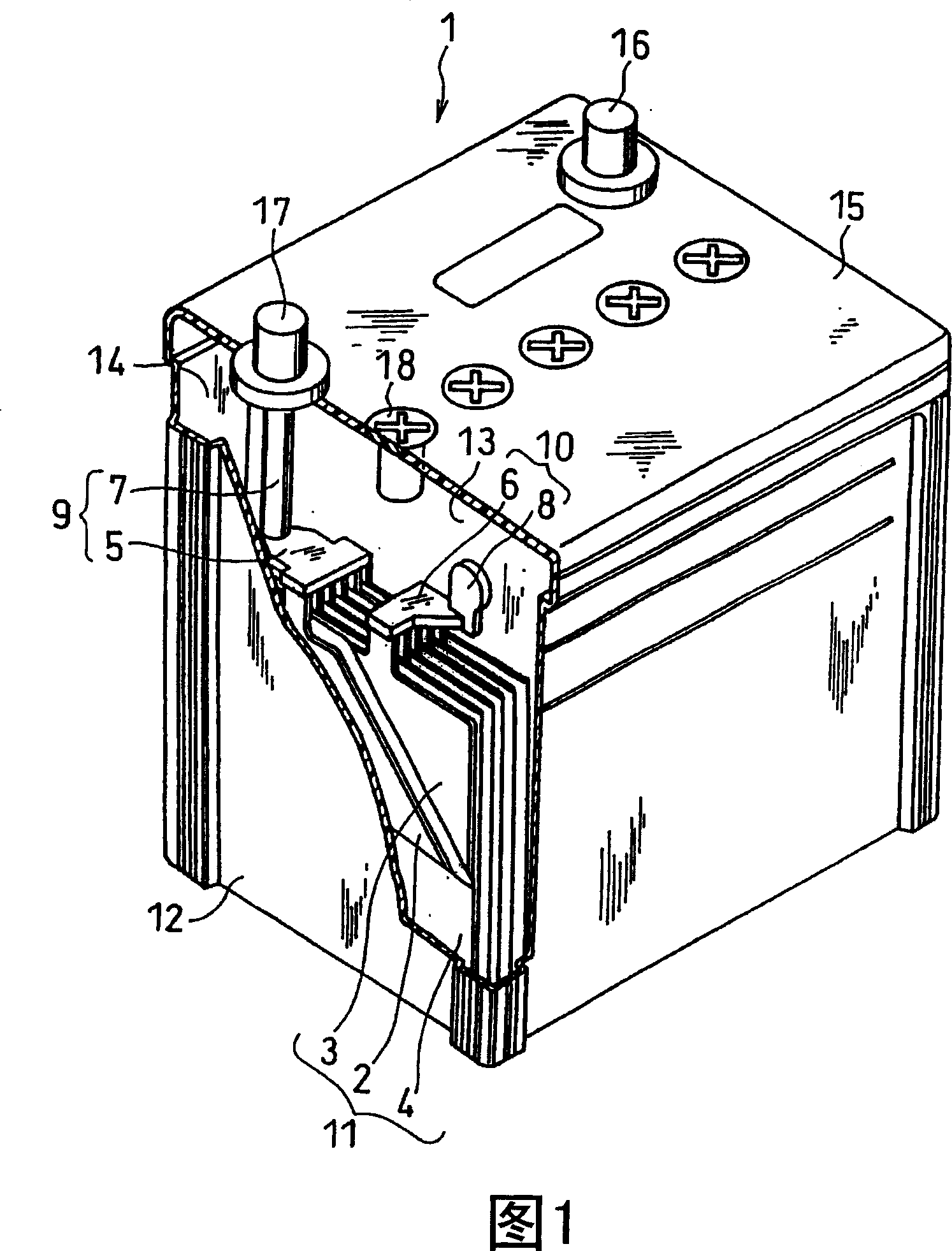
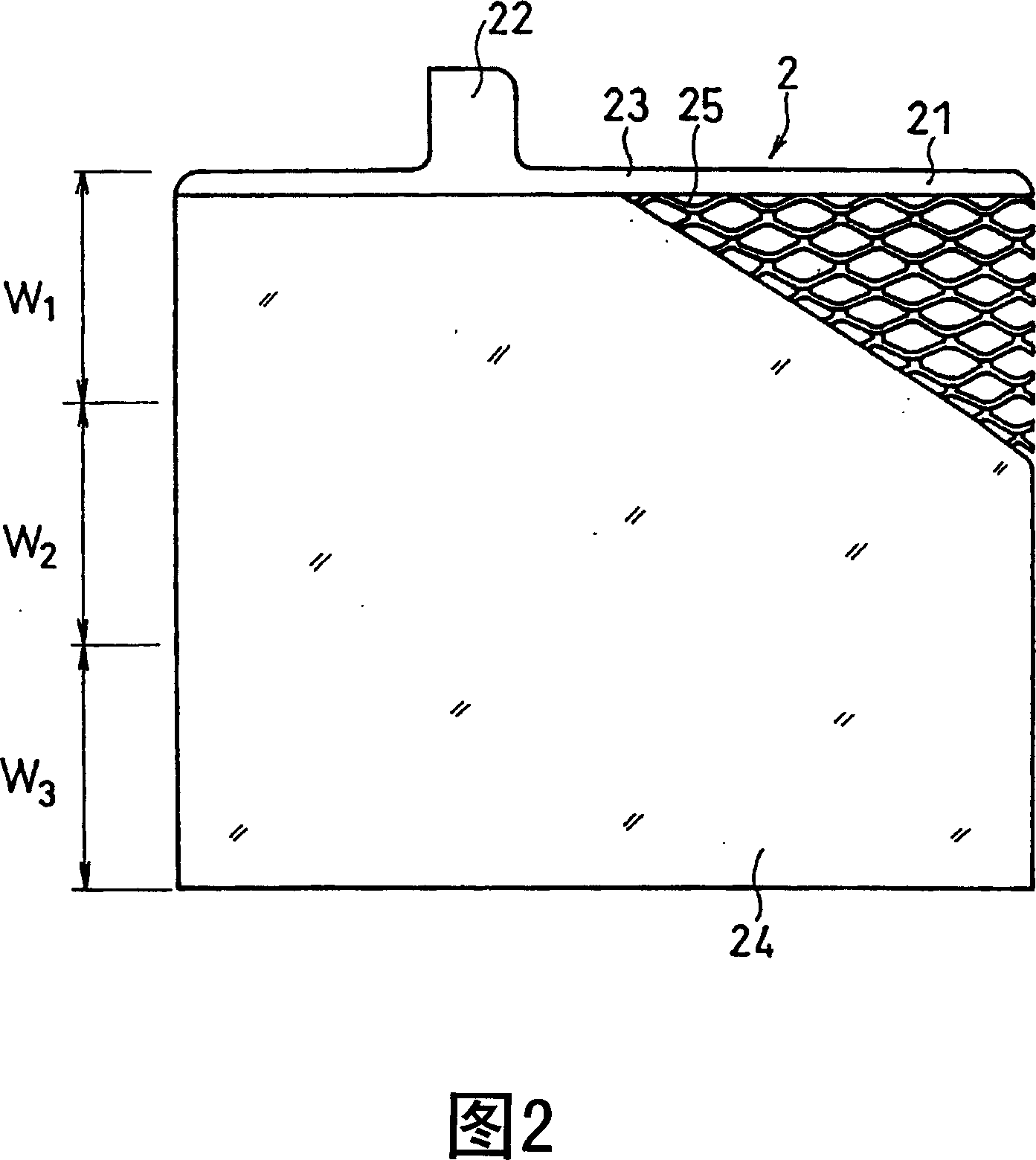
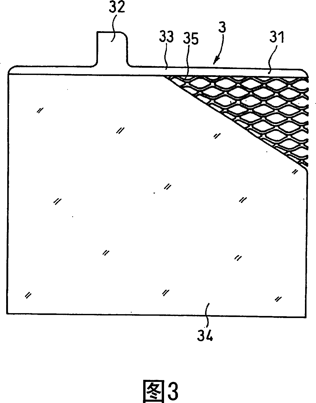

Image

  • Lead storage battery
  • Lead storage battery
  • Lead storage battery

Examples


example 1

[0102] (1) Manufacture of bag-shaped spacers

[0103] Silica particles, mineral oil, and carbon powder were added to polyethylene having an average molecular weight of 8,000,000, and stirred. After the kneaded mixture was molded by extrusion, the mineral oil was removed by a solvent such as hexane to obtain a polyethylene sheet containing silica particles having fine pores with a pore diameter of not more than 1 μm and having a thickness of 0.2 mm. The polyethylene sheet thus obtained was folded in two, and a bag-shaped spacer having an opening only in the upper portion was obtained by welding both end sides of the folded sheet with heat.

[0104] For the silica particles, porous particles (particle diameter: 20 μm) having fine pores with an average pore diameter of not more than 20 μm are used.

[0105] (2) Manufacture of negative electrode plate

[0106] The raw material lead powder (a mixture of lead and lead oxide), water, dilute sulfuric acid, and an expansion agent suc...

example 2

[0156] A glass fiber mat maintaining a thickness of 1.0 mm of silica particles was obtained by a papermaking process of glass fibers in an acidic aqueous solution in which silica particles were dispersed. Then, the obtained glass fiber is folded in two, and the left end portion and the right end portion are welded by heating to obtain a bag-shaped spacer having an opening only at the top. At this time, the silica particle content in the separator including the glass fiber mat holding the silica particles was set to become 0%, 5%, 10%, 40%, and 50% in mass. For the silica particles, the same silica particles as in Example 1 were used.

[0157] As shown in Tables 3 and 4, by combining separators comprising glass fiber mats holding silica particles with different silica particle contents, negative active material layers with different Sb contents, and Positive and negative electrode connection members, cells K1 to K5, L1 to L5, M1 to M5, N1 to N5, O1 to O5, P1 to P5, Q1 to Q5, R...

example 3

[0175] By the same method as the negative electrode grid in Example 1, in the extrusion step of manufacturing the positive electrode grid, the lead alloy sheet was extruded so as to be attached to the base material sheet to obtain a composite sheet, which was formed on a base material having a thickness of 1.1 mm. On one side of the layer there is a lead alloy layer with a thickness of 20 μm. A Pb alloy containing 5.0% by mass of Sn was used for the lead alloy flakes. The same positive electrode grid as in Example 1 was used for the base material sheet.

[0176] For the portion of the sheet of base material onto which the lead alloy flakes are to be extruded, only the portion where the expanded mesh and the frame are to be formed in the expansion process mentioned later is extruded, and the lead alloy flake is not extruded to the substrate On the central portion of the sheet of material in which the tab for the positive electrode grid will be formed, as shown in Example 1.

[...


PUM

PropertyMeasurementUnit
Thicknessaaaaaaaaaa
Lengthaaaaaaaaaa
Widthaaaaaaaaaa

Abstract

A lead storage battery comprising a pole plate group consisting of a plurality of positive and negative pole plates having active material layers held on lattices having lugs and a plurality of separators for separating the above positive and negative pole plates, and positive and negative pole connecting members consisting of pole shelves having the lugs of respective pole plates connected together and pole pillars or pole connectors provided on the shelves. A lead storage battery has been used for starting a vehicle engine or the like and the mounting of an idle stop system or the like for stopping an engine when a vehicle is at a short halt has been studied in view of environmental protection; because a lead storage battery is not charge during an idle stop, charging and discharging are repeated frequently in a low-charged region, posing such a problem that the lug of a negative pole lattice is corroded. The problem is resolved by a lead storage battery having positive and negative pole plates and positive and negative pole connecting members consisting of a Pb alloy containing Ca or Sn, negative pole lattices excluding lugs further containing Sb, separators containing silica, etc.

Description

Field of Invention [0001] The present invention relates to lead storage batteries. More particularly, the present invention relates to the improvement of the service life characteristics of lead-acid batteries for vehicles equipped with stop-and-go-systems. Background technique [0002] Conventionally, lead-acid batteries are used for starting the engine of the vehicle and for backup power. In these uses, the lead-acid battery used to start the engine supplies power to various electrical and electronic devices mounted on the vehicle, in addition to being used as a battery motor to start the engine. After starting the engine, the lead-acid battery is charged by the alternator. The output voltage and output current of the alternator are set so as to maintain the SOC (state of charge) of the lead battery between 90% and 100%. [0003] In recent years, in view of environmental protection, there has been an increasing demand for improving the fuel efficiency of vehicles. For ...

Claims


Application Information

Patent Timeline
IPC IPC(8): H01M10/12H01M2/16H01M4/74H01M4/68H01M50/446
CPCY02E60/126Y02E60/10Y02P70/50
Inventor 杉江一宏下田一彦室地省三吉村恒典岩崎真一堀江章二榑松道男米村浩一
Owner GS YUASA INT LTD
Why Eureka
Try Eureka