Luminescent element material and luminescent element comprising the same
What is AI technical title?
AI technical title is built by Patsnap AI team. It summarizes the technical point description of the patent document.
A light-emitting component and component technology, which is applied in the direction of luminescent materials, electrical components, electric solid devices, etc., can solve the problems of poor color purity, cloudy film, and shortened component life.
Inactive Publication Date: 2007-05-02
TORAY IND INC
View PDF2 Cites 3 Cited by
Summary
Abstract
Description
Claims
Application Information
AI Technical Summary
This helps you quickly interpret patents by identifying the three key elements:
Problems solved by technology
Method used
Benefits of technology
Problems solved by technology
[0005] However, conventional luminescent materials, hole transport materials, and electron transport materials are often poor in durability, and crystallization occurs due to heating of the element due to long-term energization, and the life of the element is shortened.
[0006] Especially in the presence of electron transport materials, even if a few existing materials are used, the desired luminous color cannot be obtained due to the interaction with the luminescent material or the luminescence of the electron transport material itself, even if high efficiency can be obtained. Luminescence, poor durability, etc.
In U.S. Patent No. 5,393,614, the specific phenanthroline derivative used in the electron transport material exhibits high-efficiency light emission, but crystallization occurs due to long-term energization, and there is a problem that the film becomes cloudy
In addition, there are quinolinemetal complexes and benzoquinoline metal complexes as substances exhibiting relatively good physical properties in luminous efficiency and durability, but since these materials themselves have high blue-green to yellow luminescence capabilities, When used as an electron transport material, the luminescence of these materials themselves is mixed, and the color purity deteriorates
Method used
Image
Click on the blue label to locate the original text in one second.
Reading with bidirectional positioning of images and text.
Examples
Embodiment 1
[0125] Embodiment 1 (synthesis of linking group-1)
[0126]Using 2.2 g of metalmagnesium, 14.8 g of 2-bromobiphenyl was Grignardized in THF, then reacted with 12.3 g of 9-xanthone at room temperature to 50° C., and treated with a conventional method to obtain 9-(2 -biphenyl)-9-xanthenol. This was heated and dehydrated in acetic acid to which a small amount of hydrochloric acid was added, and treated by a conventional method to obtain Linker-1 (8.5 g) represented by the following formula. 1 H-NMR (CDCl 3 , ppm): 7.8(d, 2H), 7.2(t, 2H), 7.2(m, 8H), 6.8(t, 2H), 6.4(d, 2H)
[0128] Embodiment 2 (synthesis of linking group-2)
[0129] Using 1.7 g of metal magnesium, 11.9 g of 2-bromobiphenyl was Grignardized in THF, and then reacted with 13.4 g of 2,4-diethyl-9-thioxanthone at room temperature to 50°C. Processed to obtain 2,4-diethyl-9-(2-biphenyl)-9-thioxanthol. It was heated and dehydrated in acetic acid to which a small amount of hydrochloric acid was added, and treated by a conventional method to obtain Linker-2 (13.8 g) represented by the following formula. 1H-NMR (CDCl 3 , ppm): 7.8(m, 2H), 7.6(d, 2H), 7.4(m, 3H), 7.2(m, 2H), 7.1(t, 1H), 6.9(s, 1H), 6.8(t, 1H), 6.5(d, 1H), 6.2(s, 1H), 2.9(m, 2H), 2.3(m, 2H), 1.4(t, 3H), 0.9(t, 3H)
[0131] Example 3 (Introduction of Acetyl Group to Linker-1: Linker-1')
[0132] Make the linking group-1 (8.5g) react with acetyl chloride 4.5g and aluminum chloride 7.5g in 1,2-dichloroethane at 50°C, and treat it with conventional methods to obtain the linking group shown in the following formula -1' (13.1 g). 1H-NMR (CDCl 3 , ppm): 8.0 (d, 1H), 7.9 (d, 2H), 7.8 (d, 1H), 7.7 (s, 1H), 7.4 (t, 1H), 7.3-7.1 (m, 5H), 7.0 ( s, 1H), 6.8(t, 1H), 6.3(d, 1H), 2.5(s, 3H), 2.3(s, 3H)
PUM
Property
Measurement
Unit
glass transition temperature
aaaaa
aaaaa
crystallization temperature
aaaaa
aaaaa
glass transition temperature
aaaaa
aaaaa
Abstract
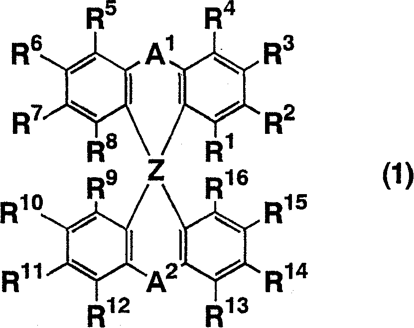
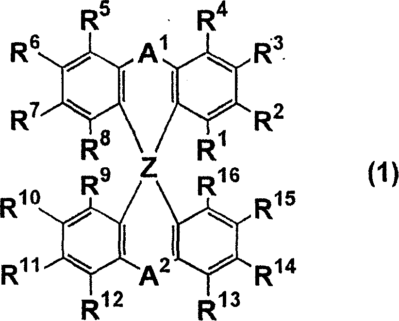
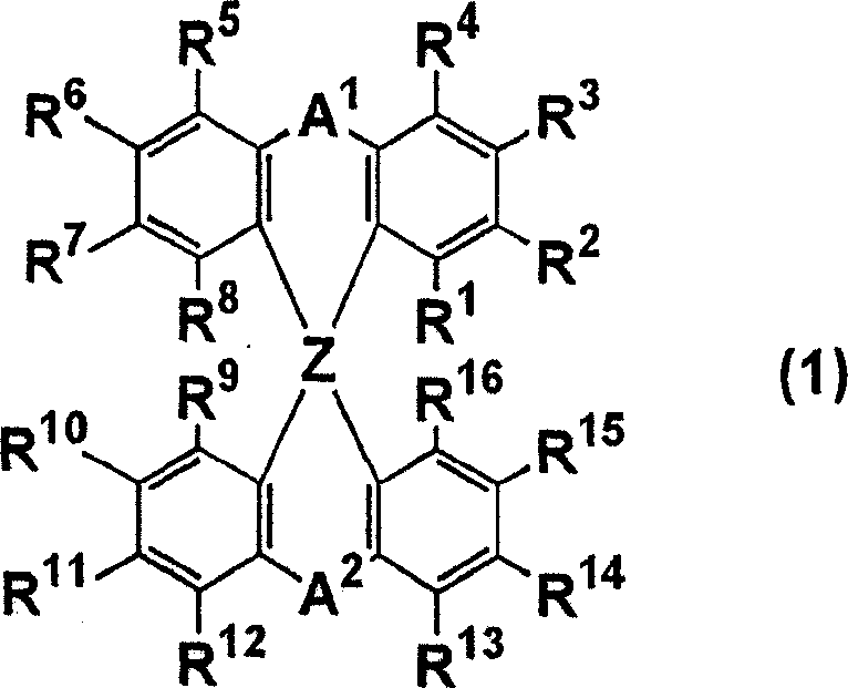
The light emitting device of the present invention relates to a light emitting device which is characterized in that it is a device with an emissive substance present between an anode and cathode, and which emits light by means of electrical energy, and said device has a spiro compound represented by general formula (1) A1 and A2 are each selected from single bonds, substituted or unsubstituted alkyl chains, ether chains, thioether chains, ketone chains and substituted or unsubstituted amino chains. However, A1<> A2. Z represents carbon or silicon. R1 to R16 are each selected from hydrogen, alkyl group, cycloalkyl group, aralkyl group, alkenyl group, cycloalkenyl group, alkynyl group, hydroxyl group, mercapto group, alkoxy group, alkylthio group, arylether group, arylthioether group, aryl group, heterocyclic group, halogen, haloalkane, haloalkene, haloalkyne, cyano group, aldehyde group, carbonyl group, carboxyl group, ester group, carbamoyl group, amino group, nitro group, silyl group, siloxanyl group and a cyclic structure formed with an adjacent substituent.
Description
technical field [0001] The present invention relates to an element for converting electrical energy into light, and relates to a light-emitting element and a light-emitting element which can be used in display elements, flat panel displays, backlights, lighting fixtures, interior decorations, signs, notice boards, electronic cameras, optical signal generators, etc. Material. Background technique [0002] In recent years, research has been active on organic laminated thin-film light-emitting devices that emit light when electrons injected from the cathode and holes injected from the anode recombine in an organic phosphor sandwiched between the two electrodes. The feature of this device is that it is thin, emits light with high brightness at low driving voltage, and can generate multi-colored emission by selecting fluorescent materials, so it has attracted attention. [0003] Since C.W.Tang et al. of Kodak Company revealed that organic laminated thin film components emit ligh...
Claims
Application Information
Patent Timeline
Application Date:The date an application was filed.
Publication Date:The date a patent or application was officially published.
First Publication Date:The earliest publication date of a patent with the same application number.
Issue Date:Publication date of the patent grant document.
PCT Entry Date:The Entry date of PCT National Phase.
Estimated Expiry Date:The statutory expiry date of a patent right according to the Patent Law, and it is the longest term of protection that the patent right can achieve without the termination of the patent right due to other reasons(Term extension factor has been taken into account ).
Invalid Date:Actual expiry date is based on effective date or publication date of legal transaction data of invalid patent.

